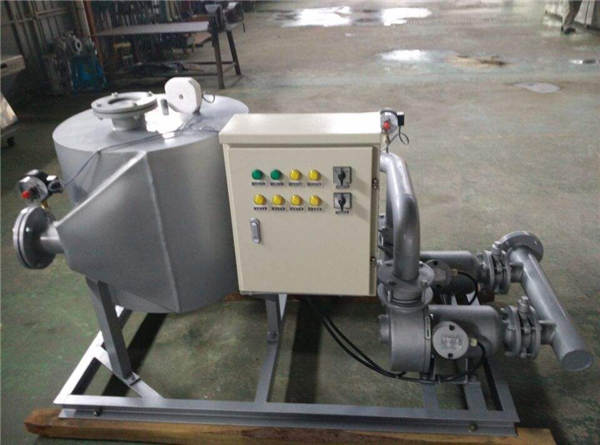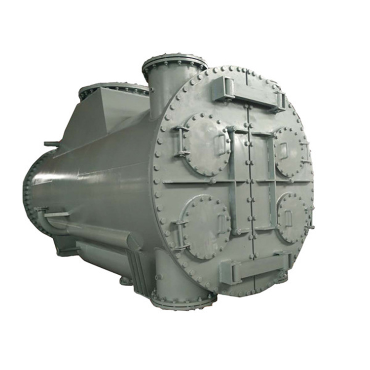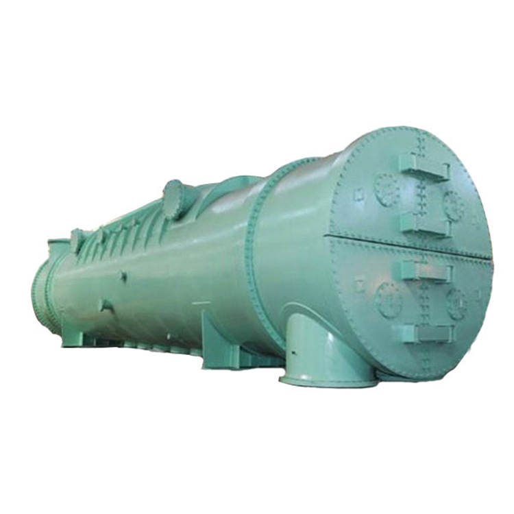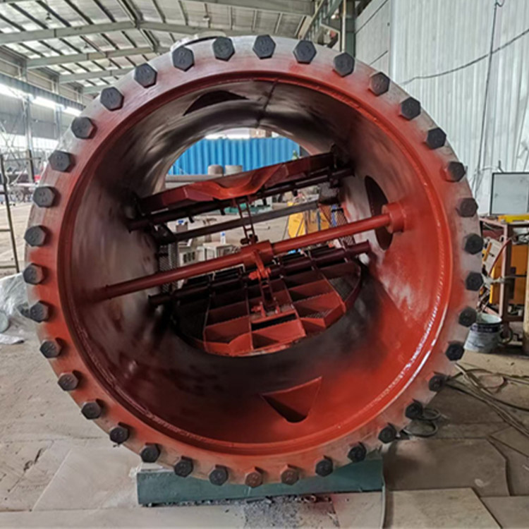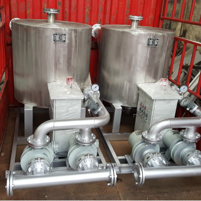


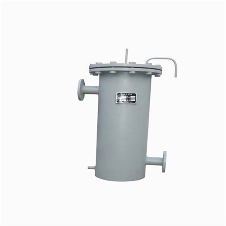

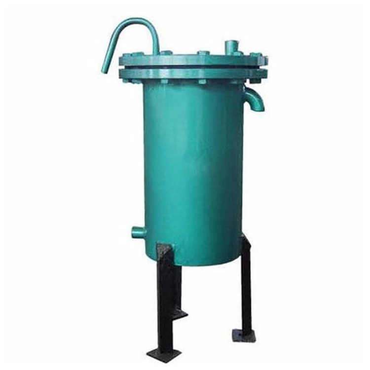
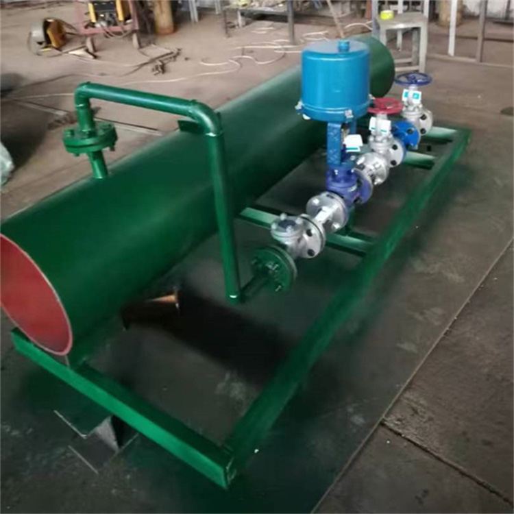


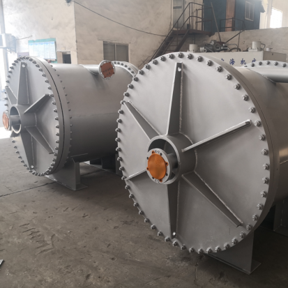

The Transformer Oil-Water Cooling Unit is a new type of heat exchange equipment with wide applications, featuring high heat transfer efficiency, low resistance loss, stable and reliable operation, compact structure, and affordable price. China began researching and manufacturing it in the late 1960s and established corresponding technical standards. With considerable experience in both manufacturing and use, it is now widely used in the petrochemical refrigeration, organic chemical food, dye, alkali, pharmaceutical, mechanical, and metallurgical industries. It has been used as a transformer cooler for nearly two decades, yielding excellent results. The Spiral Oil-Water Cooling Unit is a helix formed by rolling two sheets of 2-3mm thick plates into two uniform spiral channels. Take-offs and flanges are welded at the ends of the two spiral channels, at the top and bottom of the helix, and tangentially at the outer edge. Each channel contains a loaded liquid (oil and water) in a full countercurrent state for heat exchange. The cooling area is the sum of the unfolded length of the two steel plates multiplied by the width of the steel plates. To enhance the rigidity of the steel plates and increase the critical pressure of the helix, fixed spacing columns of a certain density are welded on the same phase surface of the two plates. This also increases the fluid's swirlability, raises the Reynolds number, and improves the heat transfer efficiency.
Due to the uniform curvature of the spiral channel, there is no significant fluid redirection, resulting in low resistance and no dead spots. To enhance heat exchange efficiency, the fluid flow rate is usually increased within the channel, which can prevent blockages from debris and also allows for self-cleaning of the channel. Additionally, both spiral channels are equipped with exhaust (liquid) ports for easy operation and can be used for sampling and testing.
Section II: Features:
High thermal efficiency
Total heat transfer coefficient can reach 3300 Kcal/m2.h°C, with better heat transfer performance than the YF (air-cooled) spiral plate cooler. The heat transfer coefficient of the spiral plate cooler is 1-3 times that of the traditional tube bundle, thereby saving energy and offering good economic benefits.
2. Low heat loss
This oil cooler features a compact structure with minimal占地面积 and exposed surface area. No insulation is required if the ambient fluid flows from the outer edge to the center of the oil cooler.
3. Reliable Structure
Oil and water channels are rolled as a whole plate, welded and sealed, ensuring that oil and water do not mix during heat exchange, thus allowing the transformer to operate safely.
4. Self-cleaning feature
This oil cooler can increase the fluid flow rate appropriately without significantly increasing the pressure drop, thereby enhancing heat transfer efficiency. The liquid flows in a spiral pattern, featuring an automatic cleaning function, making it less prone to dirt accumulation. This reduces downtime for maintenance and saves on repair costs.
III. Technical Specifications:
1. Nominal pressure is specified as 0.6 Mpa (Note: This refers to the working pressure the single channel can withstand; our factory's test pressure is 1.25 times the design pressure).
2. Operating Temperature Range: Carbon steel heat exchangers allow a temperature range of 1℃ to +200℃, while stainless steel heat exchangers permit a range of 1℃ to +300℃. The temperature and pressure increase range for carbon steel heat exchangers should follow relevant operational regulations.
3. When selecting equipment, appropriate process calculations should be used to determine the suitable working state of the fluid, ensuring that the fluid within the oil cooler channels achieves turbulent flow (typically, liquid velocity ≥ 1 m/sec, gas velocity ≤ 10 m/sec).
4. Users can select different materials based on varying operating conditions.
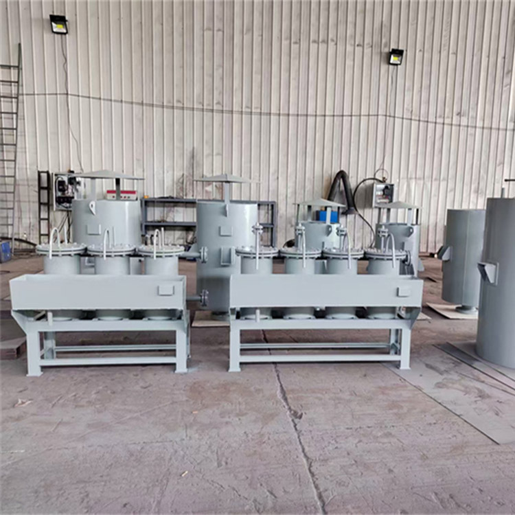
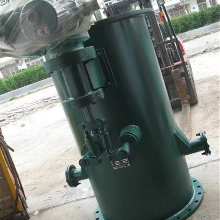
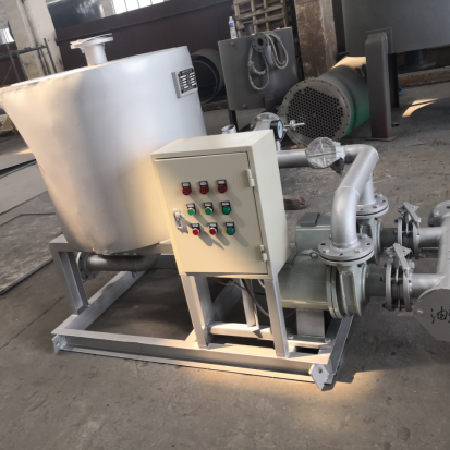
5. When using a single cooler, it is generally equipped with two oil pumps, one in use and the other as a spare. If a single unit cannot meet the operational requirements, multiple units can be used in combination; however, the assembly must comply with the following specifications:
① Parallel combination: Limited to heat exchangers of the same specification.
② Series Combination: The plate width and channel spacing of the heat exchanger should be the same.
③ Mixed Combination: One channel in parallel, another in series, limited to heat exchangers of the same specification.
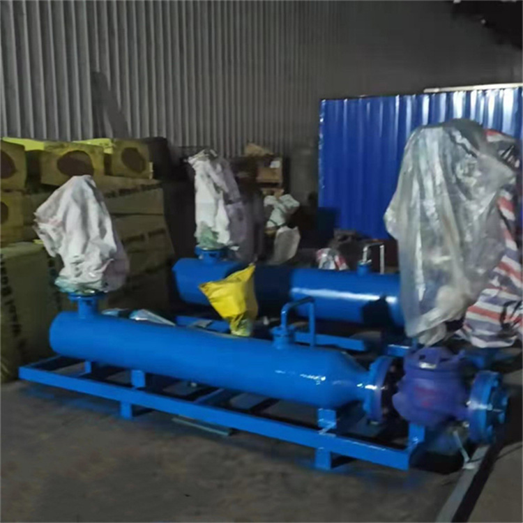
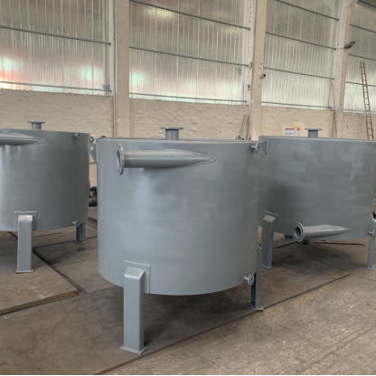
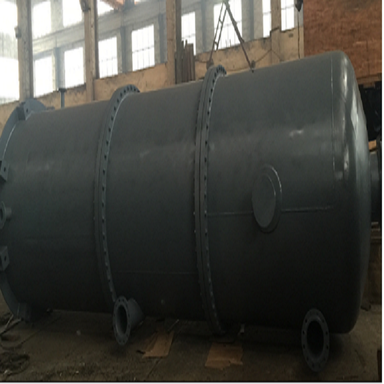
6. Installation Types: Horizontal and Vertical. Vertical installation is used to ensure that the material is completely drained after parking.
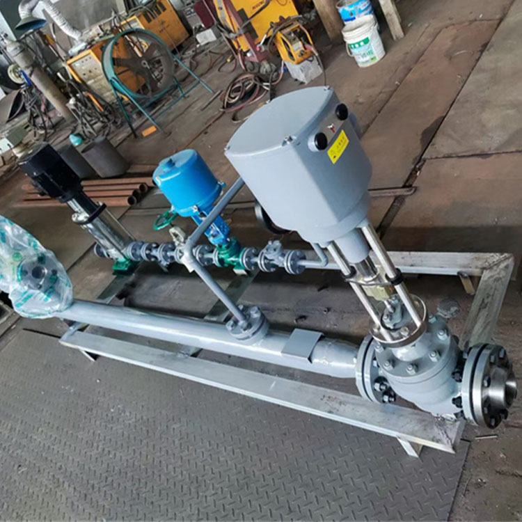
7. The orientation of the oil cooler's inlet/outlet pipes is as per the product's factory drawings, and the pipe nominal diameters are selected according to Table 1. If the customer has special requirements, they may negotiate with our technical department. After the customer selects the specifications, they can write to us to request a reference drawing of the external dimensions.