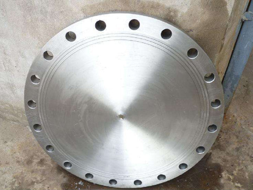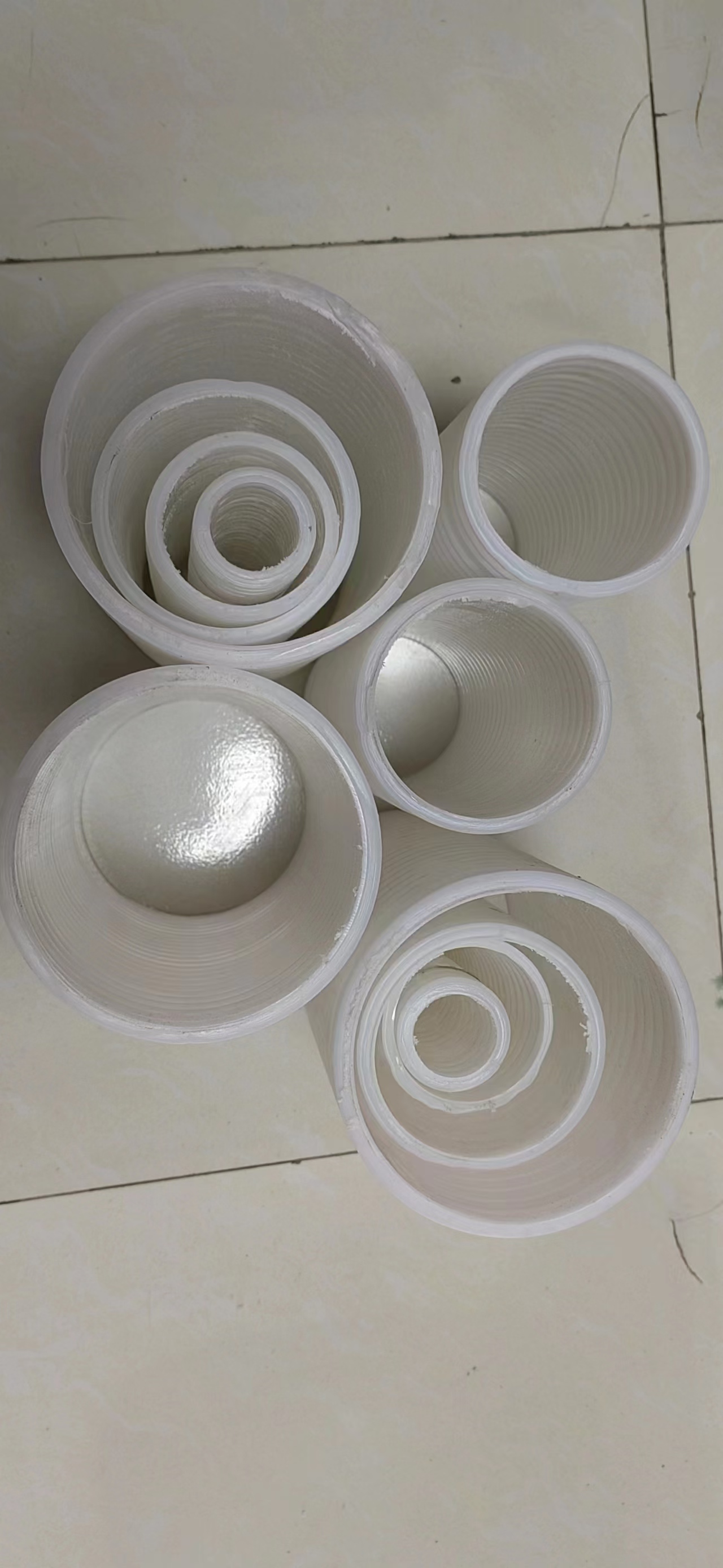

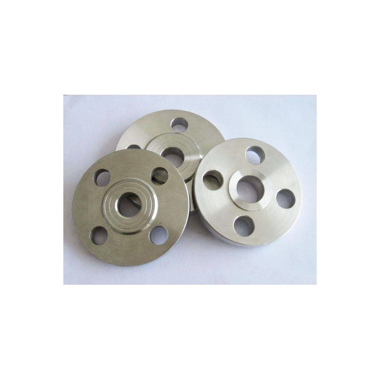


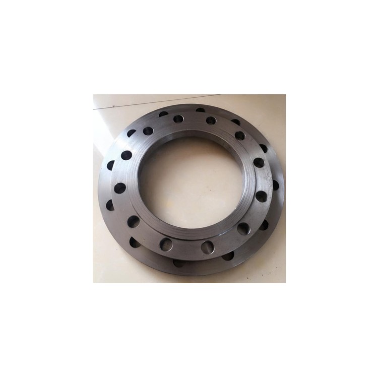


Flanges, including circular covers, are uniformly distributed with a ring of fasteners on the inner end face of the circular cover. The fasteners have an L-shaped structure, with the long side of the L-shaped fastener connected to the circular cover, and the short side facing outward. The short side of the L-shaped fastener forms a slot with the inner end face of the circular cover, where the depth of the slot is greater than the thickness of the short side of the L-shaped fastener.
A blind flange can be quickly clamped to a pipe with a corresponding slot by means of an L-shaped clip set on the inner end face, allowing for preliminary fixation of the blind flange to the pipe between the bolted joints, ensuring the installer can safely proceed with the subsequent bolt securing.
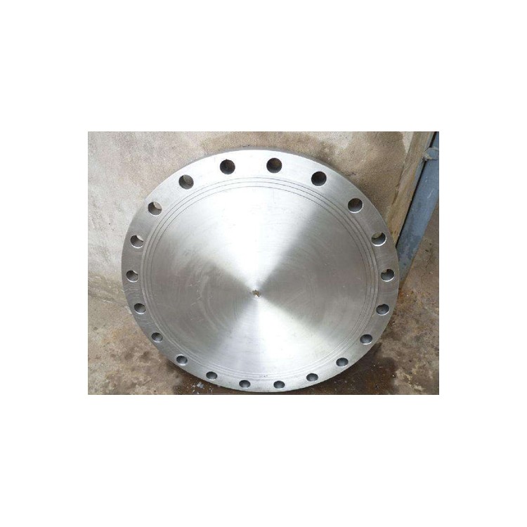
Blind flange standards are numerous, such as JB/T, SH/T, HG/T, GB/T, ASME, DIN, JIS, BS, ISO, EN, etc. First, we need to determine which standard system applies, like in the petrochemical industry, it's primarily HG/T and SH/T. Next, we need to specify the dimensions, such as the model and pressure, which is also crucial. Knowing the pressure can filter out some standards, for instance, with a pressure of 150LB, the remaining standards are SH/T, HG/T, GB/T, and ASME. Regarding Φ=220, this data is judged to be the outer diameter of the blind flange, based on personal analysis and judgment, it should be a DN100 blind flange (assuming it's not a non-standard flange or blind). The corresponding standards include GB/T9123-2010, HG/T20621-2009, JB/T86-94, DIN, BS, ISO, etc. The size suggests a PN10Bar or PN16Bar, DN100 specification.