


Plastic manhole
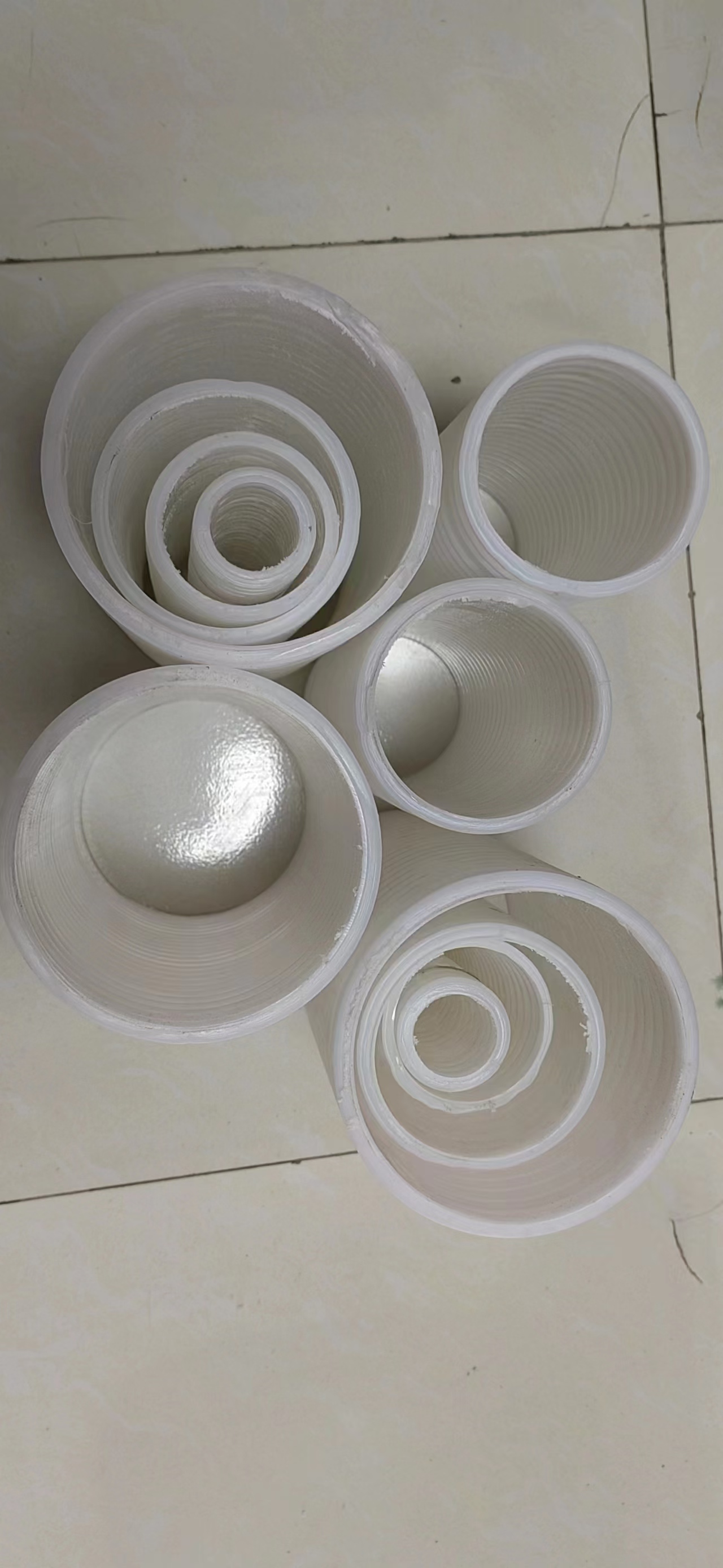
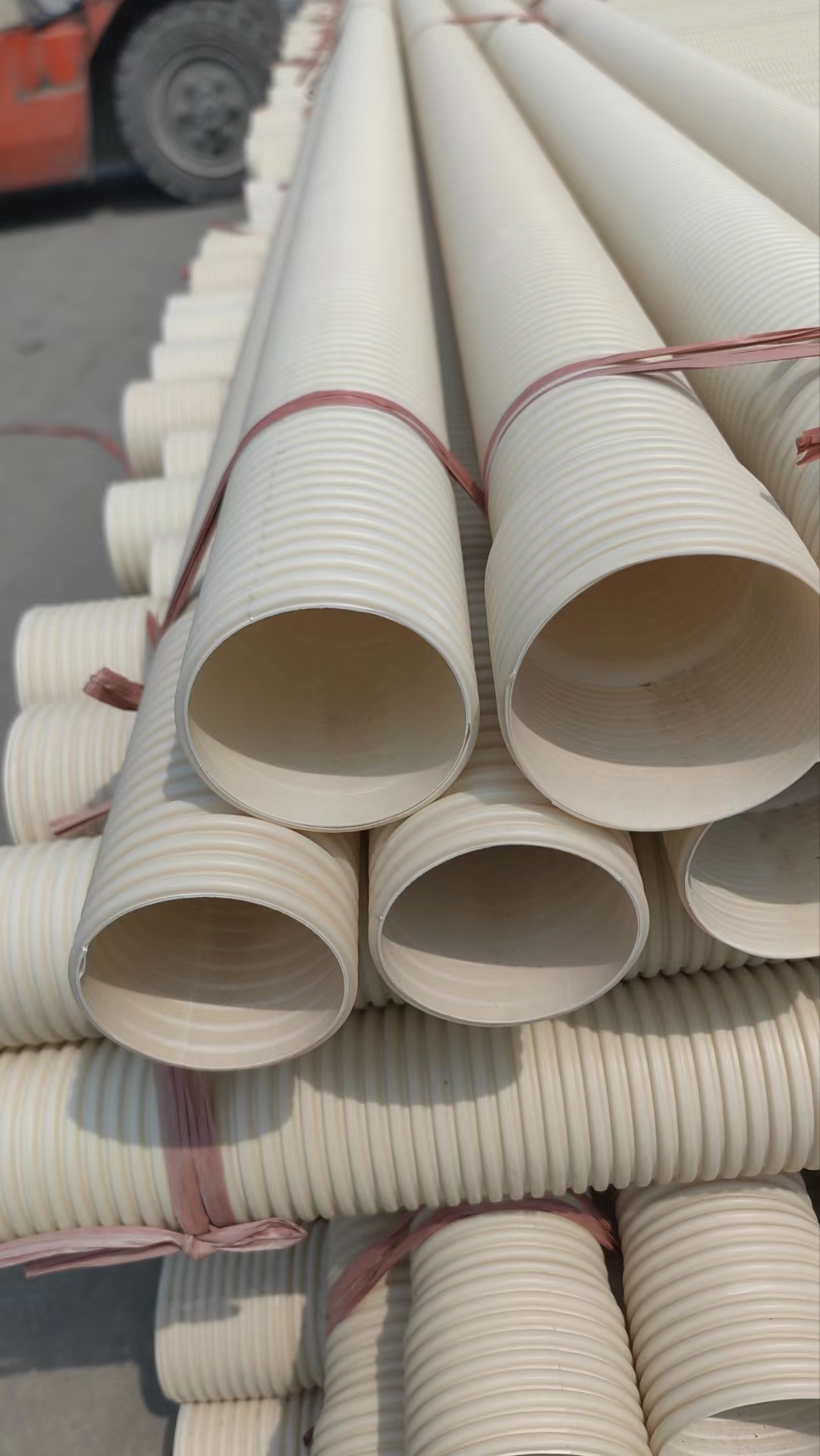
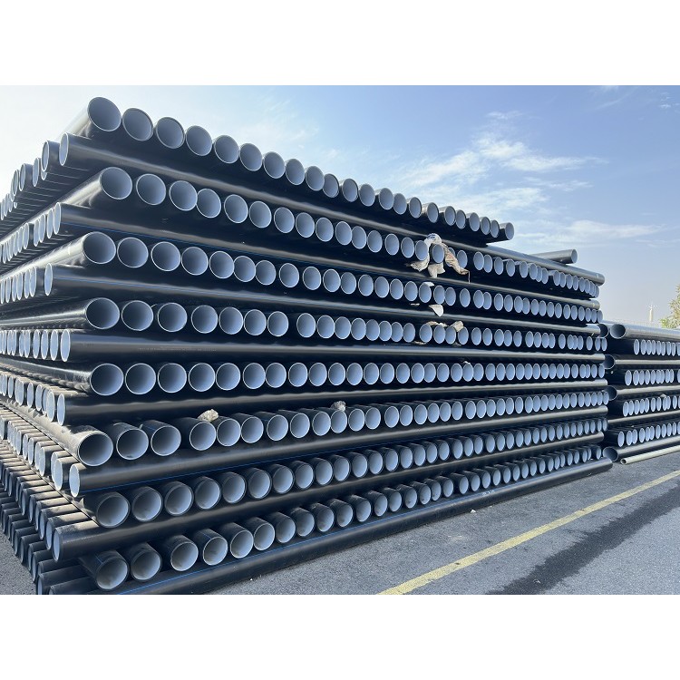
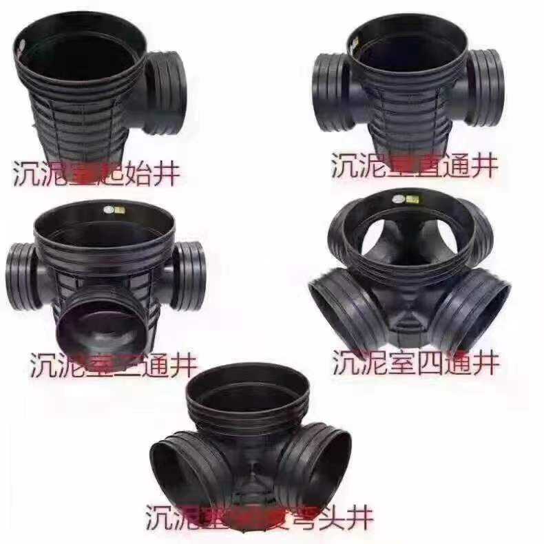
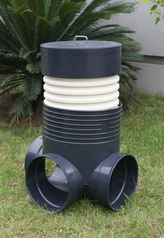
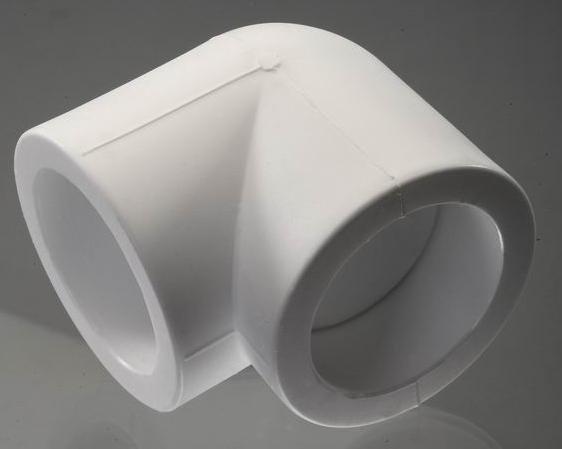
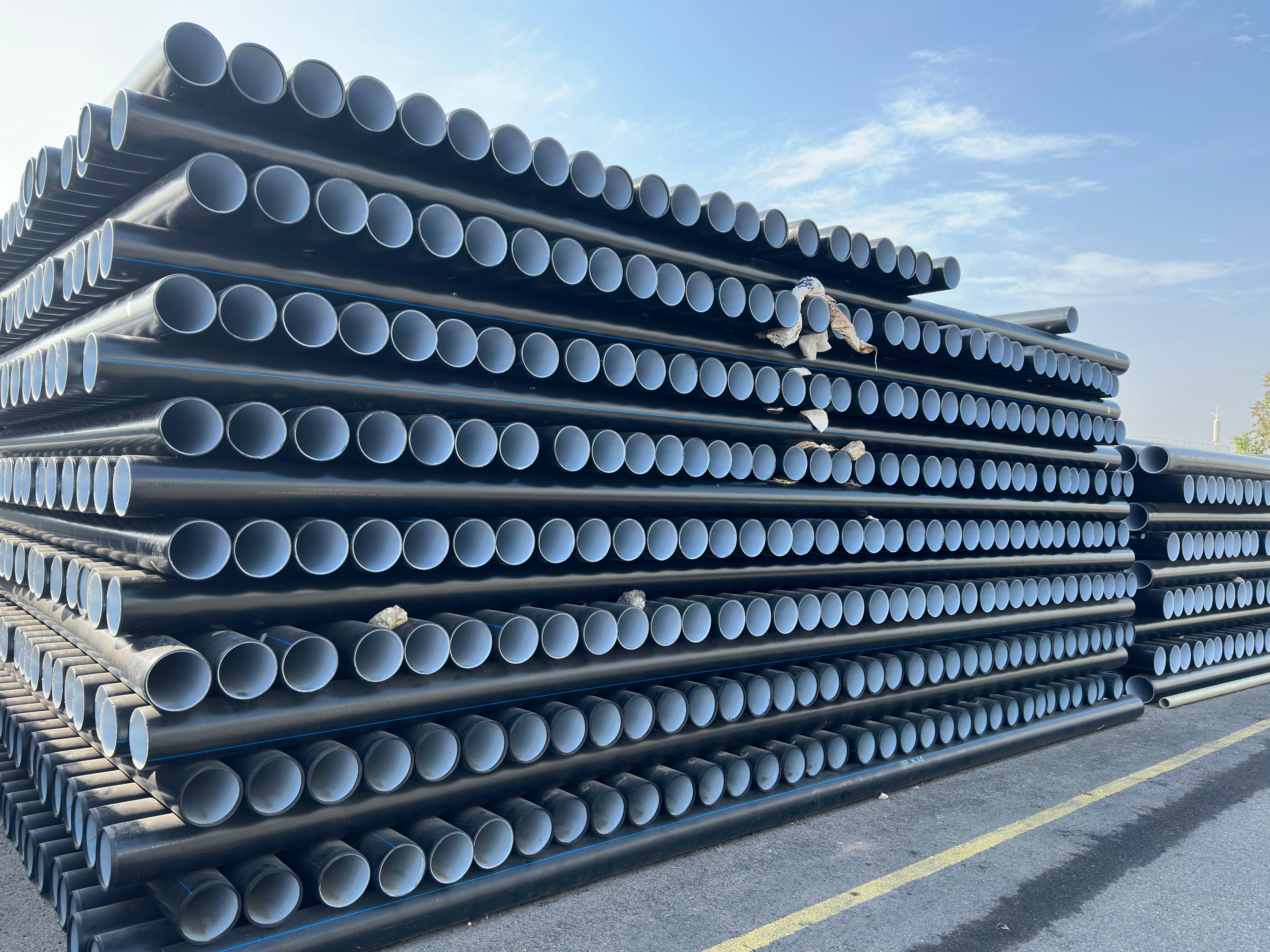
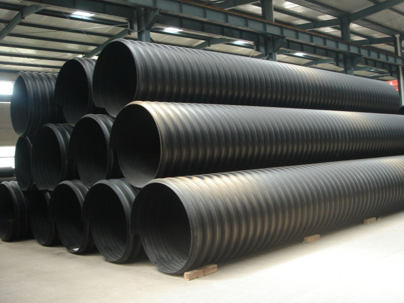
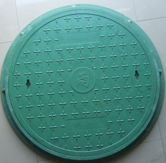
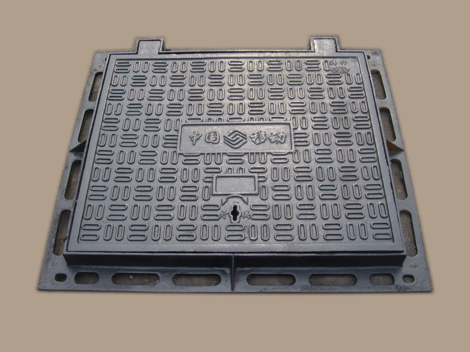
The plastic inspection well is composed of the well base, well cylinder, well cover, and plastic inspection well accessories. The well cylinder can be made of buried drainage pipes such as PVC-U double-layer axial hollow pipes and HDPE hollow spiral pipes. There are starting well bases, straight-through well bases, three-way well bases, four-way well bases, and 90-degree elbow well bases, etc., depending on the number and angle of the outlets. To accommodate various drainage conditions, the plastic inspection well is also equipped with accessories such as inner and outer diameter transition connectors, saddle joints, reducing joints, junction joints, and angle change joints. These accessories, along with the well bases, ensure the flow and sealing integrity of the entire drainage system. The well cover can be made of cast iron, composite material, or steel fiber reinforced concrete inspection well covers. The quality meets the requirements of the current "Plastic Inspection Wells for Building Area Drainage" CJ/T233-2006. The color is white or gray, and the inner and outer walls of the well cylinder should be smooth and flat, without bubbles, cracks, indentations, uneven coloration, or decomposition变色 lines. The plastic well cylinder base withstands 15KN static load pressure without cracking or fissures.
Application Range of Plastic Inspection Manholes:
Design, construction, and maintenance of plastic drainage inspection wells with an external diameter not exceeding 1200mm and a burial depth not exceeding 8m, within residential areas, public building zones, industrial zones, urban and rural municipal areas, and reconstruction of old cities.
2) Plastic drainage inspection well construction under general soil, soft soil, seasonal frozen soil, and collapsible loess soil conditions.
3) Seismic fortification for areas with a crack resistance of 9 degrees and below.
4) The ground load for general traffic lanes is designed based on a total vehicle weight of 15t (rear wheel load of 5t); for fire lanes, the ground load is designed for a total vehicle weight of 30t (rear wheel load of 6t).
5) Groundwater level is designed at a depth of not less than 1.0 meter below ground level.
The functional advantages of plastic inspection manholes mainly include five points:
Space-saving, energy-saving, water-saving, material-saving, and environmentally friendly.
(1) Acid and alkali resistant, aging-resistant, with a long service life.
(2) Environmental-friendly. The material for the plastic inspection well is odorless high-density polyethylene plastic, which is recyclable after use. It falls under chemical environmental-friendly building materials, in line with the national environmental protection policy.
(3) Uniform settlement and compressive resistance. The flexible connection between the pipeline and the well base allows the clay to move together with the pipeline, effectively addressing the uneven settlement issue that arises from the traditional connection between manholes and plastic pipelines, and effectively preventing ground collapse.
(4) Easy and quick construction. Utilizes a split assembly structure, allowing the well shaft to be cut and adjusted on-site, accommodating various installation depth requirements. It effectively reduces construction time, increasing the progress by 10-20 times more than traditional manholes; and can be constructed at any time of the day, far surpassing brick-lined manholes and other cement brick wells.
(5) Drainage: The inner wall is smooth and fluid, with guiding grooves to prevent debris from sticking, reducing the likelihood of blockages. It boasts excellent drainage capabilities, with a rainwater and wastewater discharge rate up to 1-3 times that of traditional manholes.
(6) Lightweight for easy transportation and installation, with high performance and strong load-bearing capacity; versatile with a wide range of varieties, allowing for adjustable wellbore height and drilling holes on the cylinder, as well as directional adjustments to meet all engineering installation requirements.
(7) Low overall cost, minimal maintenance fees, and superior to traditional manholes; recyclable and reusable, offering significant social benefits.
(8) Excellent sealing performance, anti-seepage. Due to the use of flexible connection method: versatile and convenient, capable of overcoming harsh construction environments such as wind, dust, and sand ash; good sealing performance can prevent the leakage of rainwater and sewage, thus preventing groundwater pollution. It can also overcome difficulties where the road elevation prevents reinsertion.
(9) Material savings. Plastic inspection manholes, made from high molecular weight resins, have replaced red bricks and concrete, conserving topsoil resources; the reduced specifications for building小区 have significantly saved on the land space required for buried inspection manholes.
Well Pit and Foundation
1. The well pit should be excavated simultaneously with the trench. During excavation, the main pipeline of the well seat should be aligned with the pipeline in the trench. The slope of the well pit should be consistent with the slope of the trench. When excavating the well pit, the foundation soil should not be disturbed; if the foundation soil is disturbed, remedial measures should be taken according to the relevant provisions of the current "Code for Construction and Acceptance of Water Supply and Drainage Pipelines" GB50268, based on the soil quality of the foundation soil. For well pits with sedimentation chamber rainwater inspection wells, the depth of the sedimentation chamber should be locally excavated according to the selected specifications. The excavation of the well pit should consider the offset factors of the main pipeline of the well seat based on the selected specifications, with the offset end pit wall aligned with the trench.
2. In areas with high groundwater levels or during the rainy season, drainage and water level reduction measures should be in place.
3. The foundation of the manhole should be determined based on local geological survey data and the calculated downward pull of backfill soil. In the absence of data, construction can proceed according to the manhole foundation plan.
Manhole adapter installation
1. Check the installation sequence of the manhole base and pipeline connection, starting from the upstream section of the service pipe, and install in the order of well-pipe-well-pipe, gradually extending downstream to the branch pipes and main trunk.
2. The construction method for the wellhead joint and pipe connection should be consistent with that of the same type of joint and pipe connection.
3. When connecting the well head with the inlet and outlet pipes, a change in diameter is required. When using a reducing coupling, if the diameter of the inlet pipe is smaller than the diameter of the well head interface pipe, the pipes should be connected with a flat inner bottom. If the outlet pipe interface of the well head is larger than the downstream pipeline, the pipes should be connected with a flat inner bottom inside.
4. When adjusting the gradient with variable angle or spherical joints on pipelines, when the pipe diameter is 315mm, tools should be used; chain wrenches are not permitted.
5. Installation of additional joints should be based on the wellbore size and the diameter of the connecting pipe. Use tools to drill holes in the well wall, ensuring the edges around the hole are smooth. The installation of additional joints must not have a reverse slope.
6. When the groundwater level is high or during the rainy season, technical measures to prevent the manhole from floating should be taken upon completion of pipeline (including manhole) installation (but prior to testing).
Casing installation
1. The wellbore length should be the height from the bottom of the socket where the wellbore connects to the wellhead to the designed ground level, minus the net distance from the wellbore to the ground. If the ground or road elevation is difficult to determine, an appropriate allowance may be reserved for the wellbore length.
2. The wellbore should be inserted into the wellbore saddle vertically. When connecting the wellbore, do not use a heavy hammer to strike; instead, use tightening tools.
Backfill
1. Backfilling should be conducted after the drainage pipeline (including pipes and manholes) has passed the acceptance inspection and should be carried out simultaneously with the backfilling of the pipeline trench.
2. Prior to backfilling, use sandbags, steel rods, and wooden supports to secure the wellhead and well casing, and ensure the accumulation of water in the foundation pit and trench is drained.
3. Backfill Material: The backfill material within the groove, ranging from the bottom foundation surface of the pipe to 0.5m above the pipe, may include crushed stone chips, sand with particle sizes less than 40mm, high (medium) calcium fly ash, medium-coarse sand, or quality soil excavated from the groove.
4. Backfill soil must not contain silt, garbage, frozen soil, and should not include stones, bricks, or other hard, angular objects.
5. When the local permafrost depth is greater than or equal to 1.0m, within the frozen ground layer, backfill with medium to coarse sand should be provided around the well bore in an area of not less than 100m.
6. Backfill should be done manually in layered, symmetrical sections, maintaining the same density as the pipeline backfill. It must not cause any displacement or inclination of the wellbore, and mechanical backfill is strictly prohibited.
Manhole cover installation
Before installing the manhole cover, measure the length of the well casing and cut off the excess part.
2. The installation of manhole covers should be determined based on the nature of the conveying medium of the inspection well. Waste water manhole covers and rainwater manhole covers, etc., must not be confused.
3. The top of the manhole with a protective cover seat should also be equipped with an inner lid.
4. Utilize C20 fine aggregate concrete for on-site casting; if reinforced concrete prefabrication is required, it must be designed separately by the structure.
Water Tightness Test
The closed water test should be conducted in accordance with the current technical specifications for buried plastic drainage pipeline engineering.
For backfill soil, generally, it should not contain stones or other hard, angular objects.
2. The layered symmetrical backfilling should be performed, ensuring no displacement or tilt occurs in the wellbore.
3. When performing layered backfilling, note that the thickness of the backfill soil for each layer should not exceed 300mm.
4. Filling should be done manually, not mechanically.
5. On each layer of backfill, use lightweight compaction tools such as wooden tamping to compact symmetrically, ensuring the density matches the pipe backfill.
6. Refilling should be conducted after the drainage pipeline has passed the acceptance inspection; Logo King Laser Engraving Machine
7. Prior to backfilling, accumulated water in the foundation pit and trench should be drained.
8. When backfilling plastic manhole covers on the road to the top of the well, the size of the foundation pit for the well cover around the well should be reserved based on the quality of the backfill soil and the characteristic value of the bearing capacity of the backfilled foundation.
9. Backfilling for plastic manholes should be done concurrently with the backfilling of the pipe trench.
10. Backfill soil shall not include silt, garbage, or frozen soil.
11. Before backfilling, use sandbags, steel spikes, and wooden supports to secure the wellhead and well casing.