
Product Details

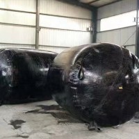
Pipe plug bladders, rubber supports, support steel plates, bowl-shaped supports, spherical supports, bridge expansion joints
价 格Negotiable
最小起订0 Piece库存0 Piece
 Business Card
Negotiable

Negotiable

Negotiable
Negotiable
 GJZf4 Rectangular PTFE Plate Supp
Negotiable
GJZf4 Rectangular PTFE Plate Supp
Negotiable
 Ball and Socket Support, Basin Su
Negotiable
Ball and Socket Support, Basin Su
Negotiable
 GPZ Series, JPZ Series Basin-Type
Negotiable
GPZ Series, JPZ Series Basin-Type
Negotiable
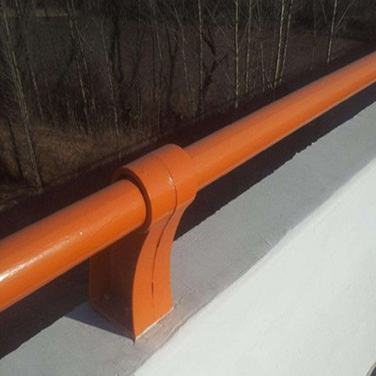 Red Bridge Guardrail Support
Negotiable
Red Bridge Guardrail Support
Negotiable
 TST Seamless Expansion Joint
Negotiable
TST Seamless Expansion Joint
Negotiable
 GPZ (Ⅲ) Series
Negotiable
GPZ (Ⅲ) Series
Negotiable
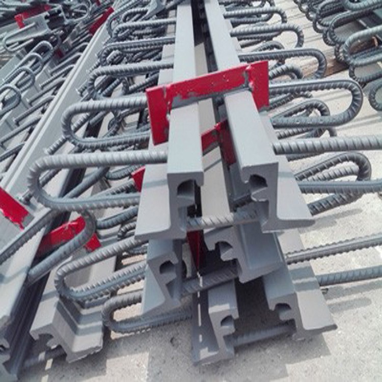
 GQF-MZL120, 160, 240, and 320 mod
Negotiable
GQF-MZL120, 160, 240, and 320 mod
Negotiable
 Customizable, design drawings
Negotiable
Customizable, design drawings
Negotiable
 GQF-C40 60 80
Negotiable
GQF-C40 60 80
Negotiable
 GQF-E40 60/80 Model
Negotiable
GQF-E40 60/80 Model
Negotiable
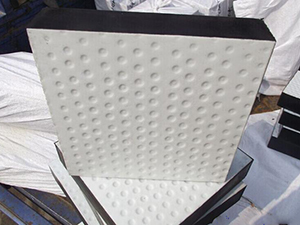
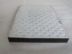
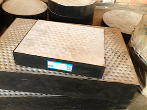
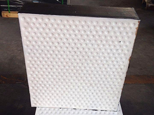
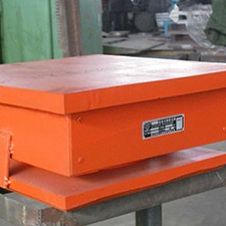
The PTFE Sliding Plate Rubber Support is a type of rubber support where a layer of 1.5mm to 3mm thick polytetrafluoroethylene (PTFE) plate is bonded to the surface of a standard plate-type rubber support. This creates the PTFE Sliding Plate Support, also known as GJZF4, GYZF4 series. In addition to all the functions of the GYZ series rubber supports, the low friction coefficient between the PTFE plate and the bottom stainless steel plate of the beam allows for horizontal displacement of the upper structure without being restricted by the shear deformation of the support itself, meeting the large displacement needs of some bridges. This plate-type rubber support, in addition to the functions of the ball crown rubber support, is particularly suitable for bridges requiring large displacements. The PTFE plate rubber support is not only technologically advanced and has excellent performance but also features simple construction, low cost, easy maintenance, and replacement, low building height, etc. Therefore, it is well-received in the bridge industry and widely used.
Four-fluoride plate-type rubber support application range:
a. Used as an activity support: Mainly for simply supported continuous slab bridges over spans greater than 30 meters, and multi-span continuous beam bridges. b. Used as slider blocks for pushing continuous beams, T-beam translocation, and large equipment sliding.
F4 rubber support load grade:
Ranging from 100KN to 10,000KN
Technical requirements for the installation of PTFE slider-type rubber supports:
A. The supports should be accurately positioned according to the design, with the top steel plate on the beam bottom tightly sealed on both sides of the four-fluorinated ethylene propylene (FEP) rubber supports. The two FEP rubber supports at the same end of a single beam should be placed on the same plane to prevent eccentric compression of the bridge supports, uneven support, and individual hollow spaces.
B. Add a stainless steel plate (thickness of 3mm) and an upper steel plate (thickness of 18mm) to the support. The lower flat surface of the upper steel plate is machined into a reverse channel shape. Insert the stainless steel plate to integrate it with the upper steel plate, and before lowering the beam, apply a thick layer of epoxy resin on the upper flat surface of the upper steel plate to bond it to the beam bottom.
C. In the凹坑 of the bracket, fill with non-volatile "295" silicone grease as a lubricant during installation to reduce the coefficient of friction. Stainless steel plates that come into contact with the PTFE board surface must not have any damage or burr to avoid increasing the coefficient of friction and damaging the PTFE board. For the upper steel plate assembly, all other parts except the stainless steel plate and the upper steel plate top surface should be coated with anti-rust paint. The relative position of the bracket to the stainless steel plate is determined by the temperature during installation.
Installation of PTFE Sliding Rubber Support:
Installation Preparation
a.1 The installation location of the plate-type rubber support should be equipped with a support stone. The flat size of the support stone should be determined based on the local bearing pressure calculation. The length and width of the stone should be at least 50mm larger than the corresponding dimensions of the support, and its height should be over 100mm. Additionally, the installation position of the jack for replacing the top beam of the support should be considered convenient.
a.2 The bearing pad stone should be equipped with a steel mesh, with a diameter of 8mm, the spacing should be 50mm×50mm. Vertical steel bars should extend from the pier and abutment into the bearing pad stone. The concrete strength grade of the bearing pad stone should not be lower than C30.
a.3 The surface of the bearing stone should be smooth, clean, dry, and free of loose sand. The elevation requirement for the top surface of the bearing stone must be accurate. Under flat slope conditions, both ends of the same beam's bearing stone and the bearing stone of the same pier or abutment on the deck should be within the same design elevation plane. The relative height difference should not exceed ±1.5 mm, and the height difference between the same bearing stone should be less than 0.5 mm.
B: Bracket Installation
b.1 Upon arrival, check for the manufacturer's trademark or identification marks on the support. During installation, mark the centerline of the support position on both the support padstone and the support according to the design drawings to ensure accurate placement of the support.
b.2 During the installation of the support, prevent uneven pressure on the support or excessive initial shear deformation. After installation, ensure that the support makes a tight contact with the upper and lower structures without any voids. For beam and plate structures that have not formed an integral unit, avoid heavy vehicle traffic.
b. The design of bridge pier and abutments should consider the need for maintenance and replacement of supports. In no case should two or more supports be installed side by side along the longitudinal centerline of the beam at the same supporting point; it is not advisable to have more than two supports on the same beam (plate); supports of different specifications should not be installed side by side.
b. After the support installation, check for any missed placements, incorrect installation direction and position (contact with the embedded steel plate, position of the support centerline), whether the support specifications and models are correct, if temporary fixation devices have been removed, and if the PTFE sliding pad supports have been injected with silicone oil (using lubricating oil as a substitute for silicone oil is strictly prohibited). If any issues are found, adjust and handle them promptly to ensure the normal operation of the installed supports, and record all deviations and abnormal conditions that occur after the support installation.
b.5 Average compressive stress on the support during use, σc = 10 MPa. Volume of the support rubber elastomer, Eb = 2000 MPa.
When in contact with concrete, the friction coefficient μ is 0.3; when in contact with steel plate, μ is 0.2; for polytetrafluoroethylene plate in contact with stainless steel plate (with silicone grease), the friction coefficient μf is 0.06. When the temperature is below -25°C, μf increases by 30%. Without silicone grease, μf should be doubled.
b.6 Install the rectangular support with the short edge aligned along the bridge direction.

Phone Consultation