
Product Details

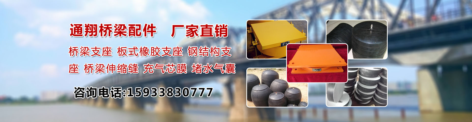
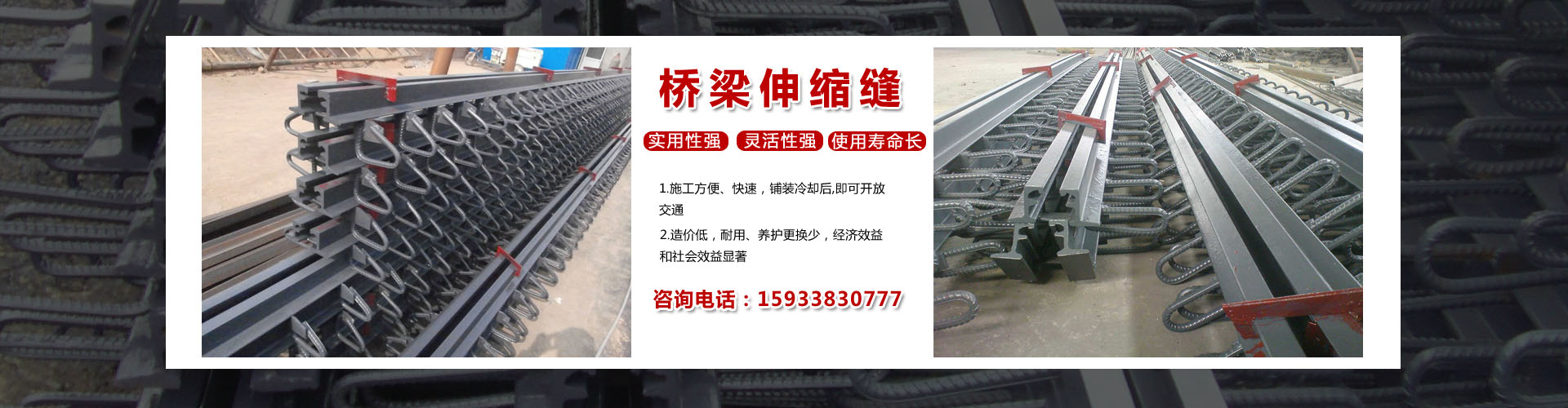
Pipe plug bladders, rubber supports, support steel plates, bowl-shaped supports, spherical supports, bridge expansion joints
价 格Negotiable
最小起订0 piece库存0 piece
 Business Card
Negotiable
Negotiable

Negotiable

Negotiable
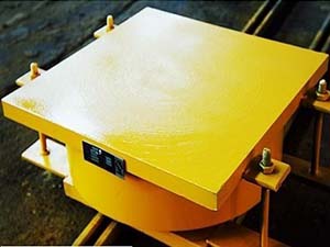
 Ball and Socket Support, Basin Su
Negotiable
Ball and Socket Support, Basin Su
Negotiable
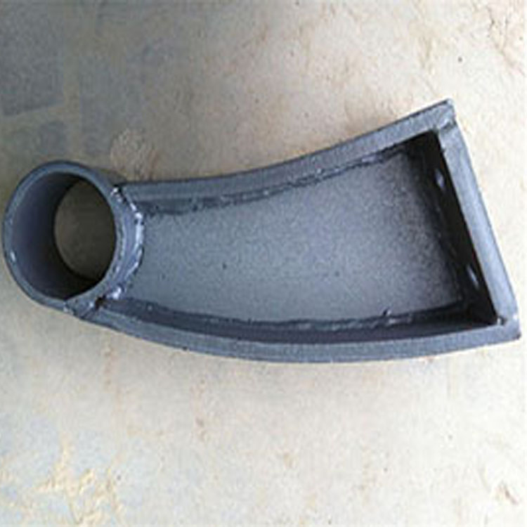 Cast Iron Molding
Negotiable
Cast Iron Molding
Negotiable
 Waterproofing Test Bladder withou
Negotiable
Waterproofing Test Bladder withou
Negotiable
 GJZf4 Rectangular PTFE Plate Supp
Negotiable
GJZf4 Rectangular PTFE Plate Supp
Negotiable
 Bridge guardrail bracket
Negotiable
Bridge guardrail bracket
Negotiable
 GYZ Series Circular Plate Rubber
Negotiable
GYZ Series Circular Plate Rubber
Negotiable
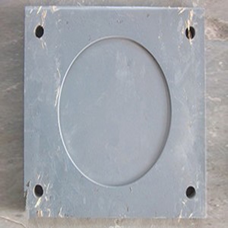 Steel plate under the bracket
Negotiable
Steel plate under the bracket
Negotiable
 GQF-MZL120, 160, 240, and 320 mod
Negotiable
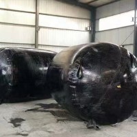
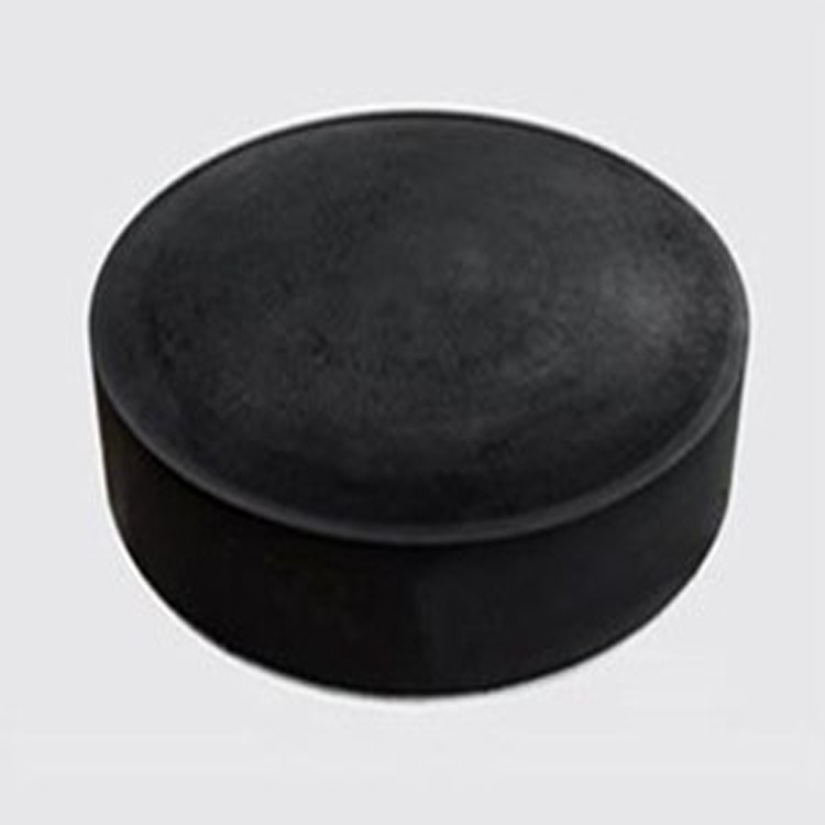
Rubber Water Plug (Airbag)
Negotiable
GQF-MZL120, 160, 240, and 320 mod
Negotiable
Rubber Water Plug (Airbag)
Negotiable
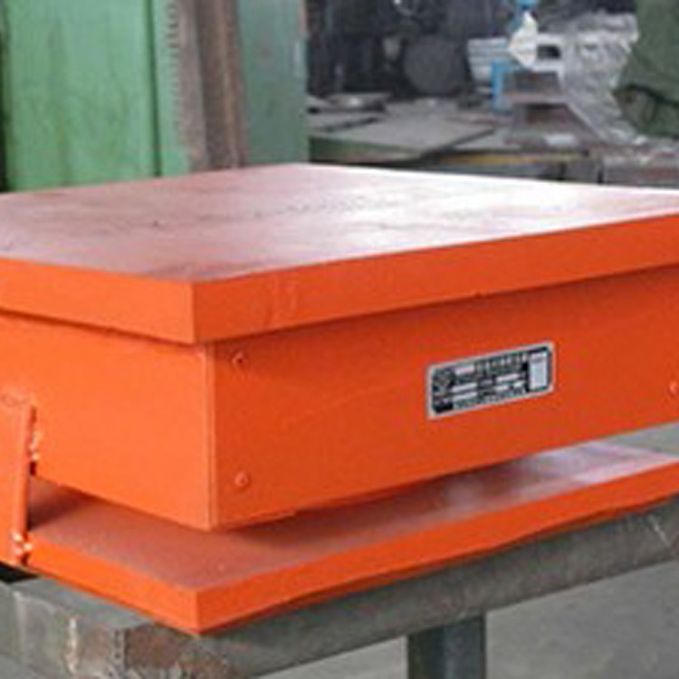
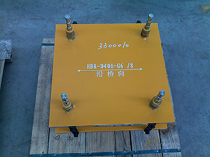
 GPZ (Ⅲ) Series
Negotiable
GPZ (Ⅲ) Series
Negotiable
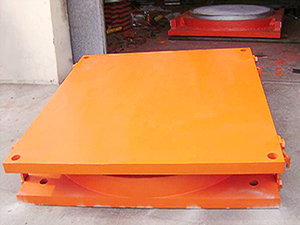
GPZ Series of Basin-Type Rubber Support and Specifications
Performance and Classification
a. Bi-directional activity support: Features vertical rotation and longitudinal and lateral sliding capabilities, code: SX.
b. Single-way activity support: Features vertical rotation and single-direction sliding capability, code DX.
c. Fixed Bracket: Only has vertical rotation capability, code GD.
Applicable Temperature Range
a. Standard Temperature Bracket: Suitable for -25℃ to +60℃
b. Cold-resistant Bracket: Suitable for temperatures ranging from -40℃ to +60℃, code F.
Technical specifications of GPZ
a. The vertical angle of the support does not measure less than 40 degrees.
b. Vertical bearing capacity (KN): 1000 to 50,000, divided into 28 grades; the uneven bearing capacity on a non-slip surface is 10% of the vertical capacity.
c. Friction Coefficient: Standard temperature type, μ≤0.04. Cold-resistant type, μ≤0.06.
d. Displacement values are shown in the table.
Product Code Representation Method
Installation of GPZ series basin-type rubber supports
Installation Preparation
1. It is recommended to set a support padstone under the pedestal base, and pre-drill bolt holes according to the spacing of the base plate bolts and the specifications of the base column. The surface of the support padstone should be level. During construction, pay attention to the elevation of the top of the support padstone to accommodate the thickness of the epoxy mortar layer under the support plate. The padstone outside the base plate should be shaped into a slope to prevent water accumulation.
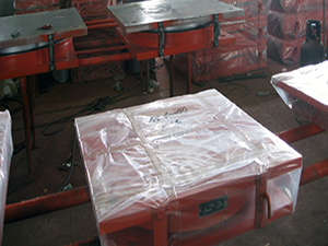
Before the bracket installation, open the box and inspect all bracket components and the packing list. Do not dismantle the bracket at will before installation.
Installation Steps and Precautions
1. Mark the centerline at the design position of the support, and also indicate the centerline on the top and bottom plates of the support.
2. Insert the base bolts into the base (roof) bolt holes and screw them into the base column. Place a rubber grommet with a diameter slightly larger than the base column support diameter between the base and the base column.
3. After the support is positioned and leveled, pour epoxy mortar or high-grade mortar into the anchor bolts and the bedding layer under the support base using epoxy mortar or high-grade mortar. After the mortar hardens, remove the shims used to adjust the support level and fill the shim location with epoxy mortar. The epoxy mortar must be poured densely.
4. When using welded connections for the support, pre-buried steel plates are installed at the top and bottom plate positions of the support. After the support is in place,焊接 should be done in a symmetrical, intermittent manner. Be cautious to prevent excessive heat from affecting the rubber and polytetrafluoroethylene plates during welding. Rust-proof treatment should be applied to the welded areas after welding.
5. If using a basin-type support for the D-shaped beam, temporary support measures should be taken at the beam ends during construction and installation to prevent lateral tilt of the lower beam. Only after the cross plates between the two D-shaped beams are welded into a single unit can the temporary supports be removed.
6. Upon unboxing the activity bracket, ensure the protection of the PTFE board and stainless steel slider to prevent scratches and dirt from adhering to their surfaces. Also, check if the 5201-2 silicone grease is fully filled.
7. The center of the support should align or be parallel to the centerline of the main beam. When installing a unidirectional sliding support, the upper and lower guide blocks must remain parallel, with the crossover angle not exceeding 5 degrees.
8. When performing system conversion cutting for continuous beam bridges and similar structures, insulation measures must be taken to prevent damage to the rubber and polytetrafluoroethylene plates.

Phone Consultation