


I. Product Applications and Advantages
Deaerators are one of the key equipment in boilers and heating systems. The severe losses caused by oxygen corrosion to the boiler feedwater pipes, economizers, and other auxiliary equipment each year have drawn increasing attention from the National Power Department. The department has issued the GB1576-2001 "Water Quality Standards for Industrial Boilers" and the "Safety Supervision Regulations for Pressure Deaerators in Power Plants," which establish departmental standards for oxygen content in deaerators. Specifically, the oxygen content in the feedwater of low-pressure deaerators should be less than 15 μg/L, and for high-pressure deaerators, less than 7 μg/L.
The rotary film deaerator differs from the existing spray and spray tray deaerators in its heat and mass transfer methods as well as deaeration capacity. It is a new type of thermal deaerator, having won the Power Ministry's New Technology and New Product Innovation Award for Scientific and Technological Breakthroughs and is listed as a key product for promotion by the Power Ministry. The rotary film deaerator has been proven to possess the following advantages after use:
High deoxygenation capability; 100% qualified oxygen content in feed water after deoxygenation.
2: Stable operation with no vibration. Suitable for vacuum start and sliding pressure operation, reducing the need for complex manual adjustments during start-up and operation.
3: High adaptability; not stringent requirements for water quality and temperature; can operate beyond capacity by 50% for short periods.
4: Steam volume less than 0.1% of the incoming water volume, no additional exhaust cooler needed; optimized equipment, reduced heat consumption value, consumes 1/3 less energy than other types of desuperheaters with the same output.
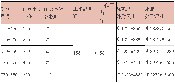
II. Technical Specifications and Matching Parameters
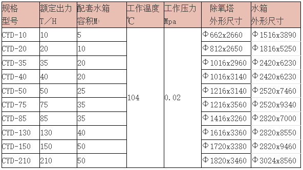
CYG Series New Type Pressure Oxygen Remover
Section 3: Structure and Principle (Illustration Included)
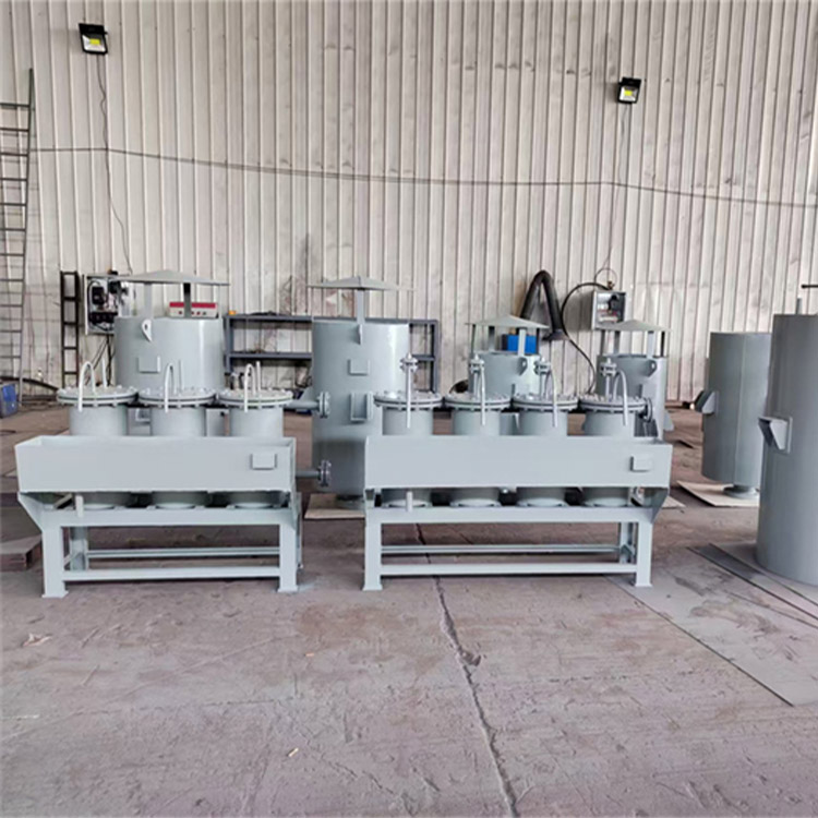
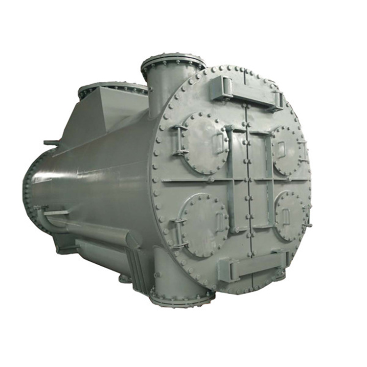
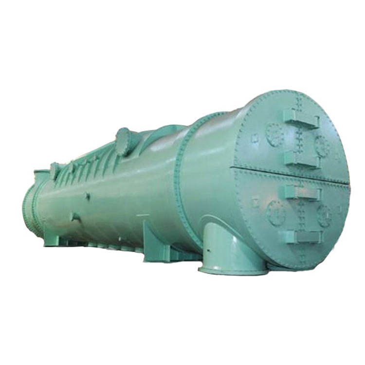
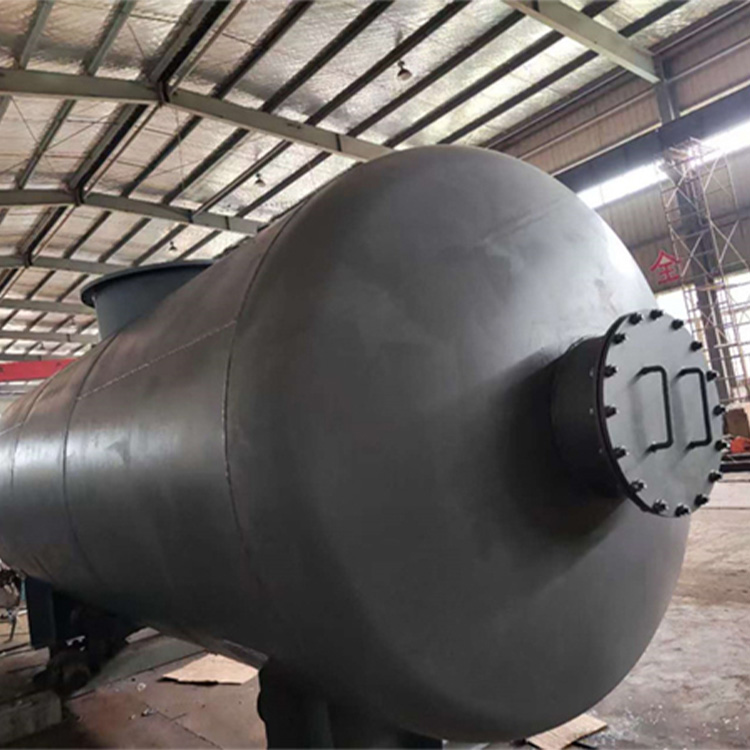
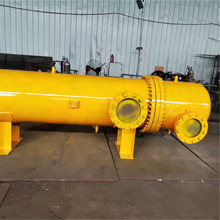
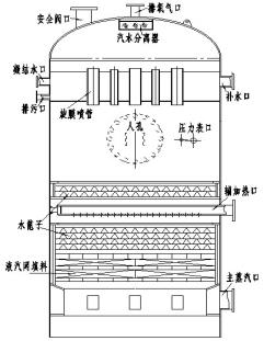
The structure of the rotary membrane oxygen scavenger consists of the oxygen scavenging head and the water tank. The oxygen scavenging head is composed of six main parts: the outer shell, the rotary membrane assembly, the water grate, the liquid-gas mesh, the steam distribution plate, and the steam-water separator. The water tank is made up of the main body and accessories.
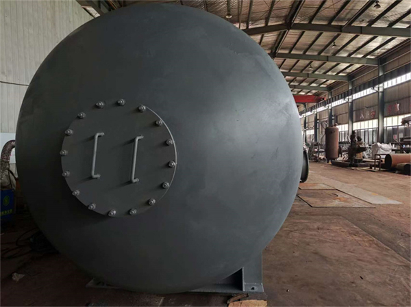
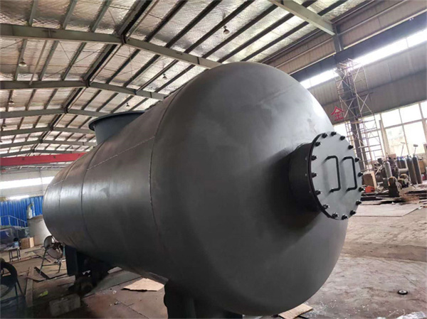
1. Shell: Welded from the cylinder body and stamped elliptical end caps.
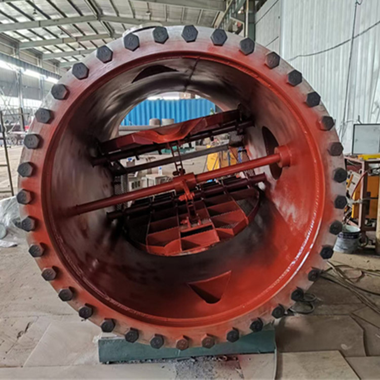
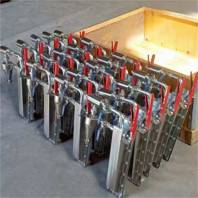
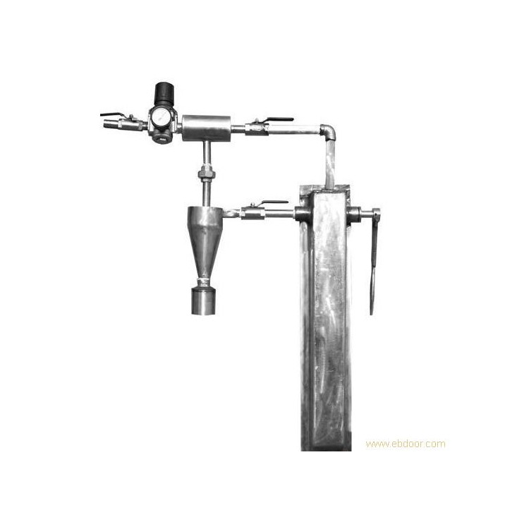
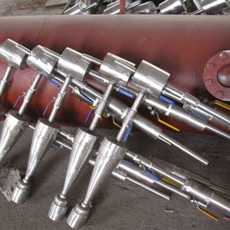
2. Membrane Assembly: Comprising a water chamber, membrane tube, condensate connection, and make-up water connection. The membrane tube and drain pipe are both made of stainless steel, requiring no maintenance throughout the year, and are a key component of the rotary membrane deaerator, removing 98% of the oxygen.
3. Drip Grating: The water supplied for oxygen removal in the membrane section and the condensate introduced through the drain pipes are here reduced in flow and redistributed, causing the water to fall evenly in a drizzle-like manner, thereby protecting the lower liquid-vapor network. The space area of the grating is not less than 50% of the total cross-section. Made of stainless steel, it operates year-round without the need for maintenance.
4. Filling Liquid-Vapor Mesh: Consists of spaced flat steel strips and a cylindrical body, internally fitted with two layers of specially designed 0.3mm stainless steel flat O-type wire mesh. Here, water is in full contact with the secondary steam, heated to saturation temperature, and undergoes deep deoxygenation to ensure the oxygen content of the deoxygenated water.
5. Steam Distribution Plate: The main heating steam is connected here, the uniform distribution structure ensures excellent heating quality, making the heating steam uniformly distributed. It rises to heat softened water under non-throttling conditions, working to deoxygenate at saturation temperature.
6. Air and Water Separator: Composed of stainless steel filling, the internal network is designed with a ventilation structure. It effectively separates and returns the water carried by the exhaust gas, making it an indispensable component to ensure the exhaust gas is free of water.
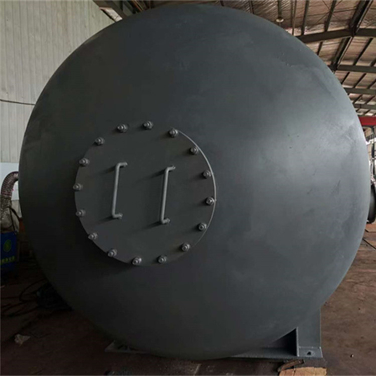
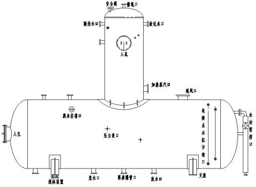
7. Water Tank: Fabricated from a cylinder body and welded with stamped elliptical heads, internally equipped with reinforcing rings. The base is mounted on a prefabricated workbench, with one end fixed and the other for installing the expansion roller assembly. The tank is equipped with inspection manholes, safety valve connection ports, drain outlets, boil-over pipe openings, water seal cylinder openings, level gauge interfaces, pressure gauge ports, temperature gauge ports, and water intake ports.
Deaerator Thermal Deaeration Basic Principle: In a container, the amount of gas dissolved in water is proportional to the partial pressure of the gas above the water surface. The main method of thermal deaeration is to use steam to heat the feedwater, increasing the water temperature and gradually increasing the partial pressure of steam above the water surface, while the partial pressure of dissolved gases decreases, causing the dissolved gases to continuously escape. When the water is heated to the boiling temperature at the corresponding pressure, the surface is entirely steam, the partial pressure of dissolved gases is zero, and the water no longer has the ability to dissolve gases, meaning that gases dissolved in the water, including oxygen, can be removed. The effectiveness of deaeration depends on whether the feedwater is heated to the boiling temperature at the corresponding pressure and on the rate of gas exclusion, which is greatly related to the size of the contact surface area between water and steam.
Principle of operation for the spiral membrane oxygen removal unit (jet, entrainment, turbulence, heat transfer, mass transfer, water film skirt, rain-like, saturated)
Condensate and make-up water first enter the water chamber of the internal spiral membrane unit in the deaerator, and under a certain pressure difference, they are sprayed diagonally into the inner cavity through small holes in the membrane tubes, forming a jet. Due to the inner cavity being filled with rising heated steam, a large amount of heated steam is drawn into the jet during its movement (tests have proven the jet's entrainment effect); a violent mixing and heating action is produced over a very short distance, resulting in a significant increase in water temperature. The rotating water continues to spiral down along the inner wall of the membrane tube, forming a swirling water film skirt (the critical Reynolds number of water in rotational flow decreases significantly, causing turbulent swirling). At this point, the turbulent state of the water has the most ideal heat transfer and mass transfer effect, and the water temperature reaches the saturation temperature. Oxygen is then separated out, as it cannot diffuse freely within the inner cavity and must rise with the steam through the exhaust pipe to the atmosphere. The feed water from the rough deaeration section and the condensate introduced through the drain pipes are mixed here for a second distribution, falling uniformly like rain onto the liquid-vapor mesh below, and are then deeply deaerated before flowing into the water tank. The oxygen content in the water within the tank is 0-7 μg/L at high pressure and less than 15 μg/L at low pressure, meeting the departmental operational standards.
Due to the vortex membrane deaerator keeping the water in a turbulent state during operation and having a sufficiently large heat exchange surface area, the better the heat and mass transfer effect, the smaller the exhaust steam volume (meaning less steam used for heating, resulting in smaller energy loss and significant economic benefits). The excellent deoxygenation effect allows the deaerator to operate beyond its capacity (typically up to 50% over the rated output) or meet operating standards under low water temperature full补水.
IV. Installation, Operation, and Maintenance
1. The installation, operation, and maintenance of deaerators, water tanks, and accessories should be conducted according to the CYD(G) type deaerator system diagram and the <<Technical Supervision Regulations for Safety of Power Station Deaerators>>.
2. The deaerator should be placed above the feed pump, with the difference in height between the lowest water level of the deaerator tank and the centerline of the feed pump not less than 6 to 7 meters. The bottom plate of the tank support should be in firm contact with the concrete.
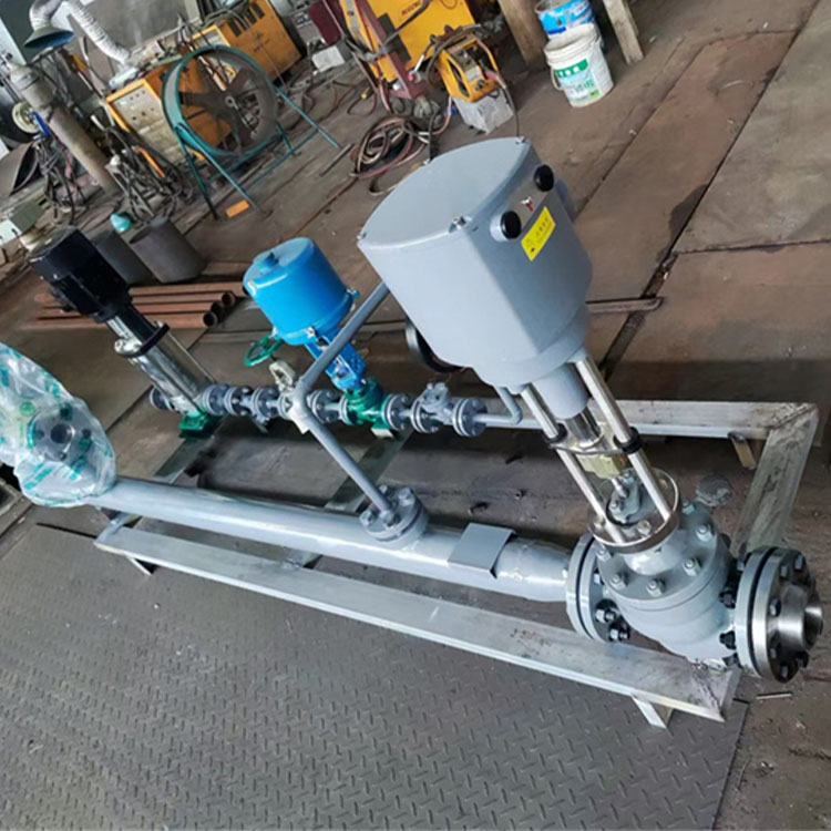
3. Install temperature transmitters and flow sensors on the deaerator's inlet water pipe, a water level transmitter on the deaerator, to detect signals such as inlet water temperature, flow rate, and deaerator water level. Input these signals into the calculation and processing module to control the hydraulic and thermal conditions of the deaerator's water intake and heating steam, ensuring the deaeration effect is achieved by maintaining the deaeration temperature at (104±1.5℃). Adjust the electric actuator on the steam pipeline to regulate the valve, heat the incoming steam, and automatically adjust the steam flow rate based on the water temperature of the deaerator. Upon stopping the water replenishment, the electric actuator automatically closes.
4. The lower part of the water tank is equipped with a reboiling tube, which is used for heating and deoxygenation during the boiler's water filling and unit startup. For the first use, when the water level in the tank exceeds half, gradually open the reboiling heating tube valve at the bottom of the tank to heat the water inside, maintaining a boiling state of the water within the tank. The use should be discontinued once the unit is started up and loaded. Additionally, a prevent-rotation plate is installed at the outlet tank opening to prevent water whirl at low water levels, thereby increasing the effective volume of the tank. Tests have shown that water whirl greatly affects pump cavitation; without a prevent-rotation plate, the water level in the tank must be maintained at three times the pipe diameter, but with the plate, it can be reduced to below 1.5 times.
5. After on-site welding of the deaerator and water tank, a hydrostatic test should be conducted. The pressure parameters for the hydrostatic test are: 0.2 Mpa for atmospheric deaerators and 0.75 Mpa for pressure deaerators. Before introducing the steam condensate into the deaerator, it should be accumulated in the intermediate storage tank as much as possible, and then evenly delivered to the deaerator to ensure stable deaerator load.
6. Oxygen Scavenger with Protective and Alarm Functions
(1) The water tank and deaerator are equipped with an adequate number of full-blow safety valves, with the quantity and specifications meeting the design technical specifications.
(2) The oxygen removal drum should be equipped with local and remote water level gauges, and be equipped with high and low water level alarms and hazardous high and low water level action devices. For controlling the oxygen removal drum's water level changes, the softening water pump (condensate pump) automatically starts to replenish the drum with water when the water level drops; the pump automatically stops when the water level rises.
7. For the cold start of the deaerator, it is recommended to preheat the shell with auxiliary steam for 10-15 minutes. Under a certain steam pressure, send the demineralized water into the deaerator head, while adjusting and increasing the steam inlet valve to heat the feedwater in the film-forming section to a temperature close to the steam saturation temperature of the deaerator operating pressure (i.e., 102-104°C).
8. Adjust the water level regulation system to maintain the water level in the tank within ±100mm of the normal level. (When both deaerators need to operate in parallel, to balance the pressure and water level inside the deaerators, each deaerator tank must have a connecting steam and water equalizing pipe. Aim for consistent pressure, water temperature, and water level.) When the water level reaches ±200mm of the normal level, the high-level drain valve (electromagnetic gate valve) should open freely to drain water, and it should automatically close when the water level decreases. During operation, regularly check the responsiveness of the electromagnetic water level regulation system and the operation of the makeup water regulating valve.
9. Gently open the top exhaust valve, open the valves on the steam piping, supply steam for heating, and record the steam pressure and temperature. Adjust the exhaust valve to typically open to about 2/3, achieving an exhaust flow of approximately 2-3 kg per ton of deoxygenated water.
10. When operating the deaerator, the inlet valve should be opened first, followed by the steam inlet valve. The sequence should be reversed when shutting down.
12. When operating the deaerator, if steam with water is observed, the following methods can be employed to address the issue:
Adjust the heating steam inlet valve
b. Inspect pressure adjustment device
c. Manual pressure reduction operation
d. Gradually close the secondary heating steam cutoff valve.
13. Test the dissolved oxygen content of the water in the sampling tank to ensure it meets the standard. If it does not, adjust the water inflow, air inflow, and exhaust flow to achieve compliance. Once qualified, you can supply water to the boiler.
14. Regularly test the oxygen content of the incoming and outgoing water at specified intervals, record the readings of various monitoring instruments, to ensure the normal operation of the deaerator.
15. Cautionary Notes
When the deaerator experiences severe vibration and water ejection, water hammer has occurred; reduce the inflow of water.
b. During operation, attention should be paid to ensure that the pressure within the deaerator does not drop sharply, and a vacuum should not be formed.
c. In case of short-term shutdown, prevent the deaerator from forming a vacuum or becoming full of air. Gently open the bypass steam valve to introduce a small amount of steam, maintaining a heated state within the deaerator head, and expel a trace of steam from the air exhaust.
d. Oxygen Remover should be inspected regularly to prevent nozzle clogging, packing corrosion or compaction, and instrument malfunction.
e. If the deaerator is out of service for an extended period, the water in the tank should be drained to prevent corrosion of the vessel.
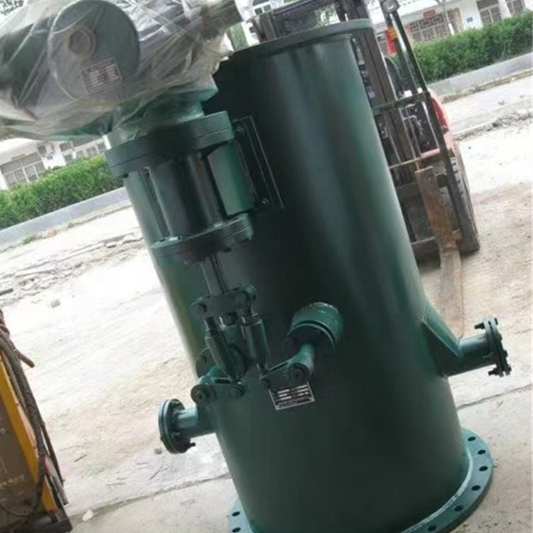
Five, Oxygen Scavenger General Accessories
·Safety Valve --- Installed on the water tank, it automatically opens to relieve pressure when the internal pressure of the equipment exceeds the allowable limit, serving as a safety protection function.
·Pressure Gauge — Installed at the top of the deaerator, monitoring the pressure inside the equipment.
· Thermometer — Installed at the bottom of the water tank, monitoring the water temperature inside.
· Butterfly valve - Installed on the heating steam pipeline, it adjusts the flow of heating steam with the aid of an automatic regulator to maintain the pressure inside the deaerator within the rated range.
· Water-seal tube --- When the liquid level rises, the pressure difference exceeds the water column pressure, causing the balance to be disrupted, and the liquid flows out through the water seal. It also serves as a pressure relief function when the operating equipment's air pressure exceeds the safe limit.
·Stop valve---Installed on the refilling pipe, it adjusts the flow of makeup water with the help of an electric water level control system to maintain the normal water level of the tank.
·Regulating Valve - Installed on the make-up water pipe, it adjusts the flow of make-up water using an electric water level control system to maintain the normal water level of the tank.
·Electrical Contact Level Monitoring——Consists of a sampling electrode point, a level monitoring cylinder with electrical contacts (primary instrument), and ultra-pure ceramic electrodes and a display instrument (secondary instrument). Installed on a water tank, it monitors the water level inside and outputs a 4-20mA signal to the control room to regulate the water level valves.
· Magnetic Flip Level Gauges --- Installed on water tanks for on-site monitoring of water levels, also capable of connecting remotely and outputting a 4-20 mA signal to the control room for adjusting the water level valve.
Balanced Tanks — Used in conjunction with pressure/differential pressure transmitters and level gauges, these tanks can reflect the deaerator's (weight) level during boiler startup, shutdown, and during normal operation.
·Electric gate valve---Installed on the water tank's discharge pipeline, it automatically opens when the water level in the tank exceeds a certain limit, using the electric water level regulation system to drain the excess water to the drain tank.
·Pressure Automatic Regulator---Automatically adjusts the opening of the heating steam inlet valve, regulating steam flow while maintaining stable pressure within the deaerator.
· Electric Water Level Regulation System - Automatically adjusts the supply water flow and controls the limit water level drain valve (electric gate valve).
Six, Order Provision Data
1: Oxygenator output (T/H) and effective volume of water tank (m³).
2: Oxygen remover working pressure, temperature...
3: Only replace the deaerator tower and provide the installation connection diagram for the original deaerator tower.
Section 7: Renovation
Our factory not only supplies complete sets of new-type water film deaerators but also undertakes renovations for power plants' spray plate and spray packing deaerators. Specifically, this includes:
The modification cost is about half the price of replacing the deaerator head.
2. Fast progress, easy to process and on-site modification installation. Utilize the original deaerator head's shell section, remove all the spray disk or spray packing components inside the original deaerator head, retain the lower steam inlet plate, then install a liquid-gas mesh and a water grate at a certain position above the lower steam inlet plate. Finally, use the annular pressure plate for sealing and fixation to prevent water-gas short-circuiting during future operation.
3. After separating the junction between the head and the cylinder, weld and install them into the film former. Connect the other pipeline components according to the provided modification scheme diagram. The job is then complete. Once inspection is passed, the equipment can be put into operation.
4. During the改造 process, the diameter of the deaerator head is generally not increased. The height is appropriately adjusted based on the specific circumstances, usually either raised or installed at the original height.