


Technical Specifications
I. Basis:
"Measurement Method for Shielding Effectiveness of High-Performance Shielding Rooms" GB/T 12190-2021
"General Technical Requirements and Testing for Shielded Rooms" GJB 20219-94
3. "Engineering and Acceptance Standards for Shielded Room Construction" SJ31470-2002
4. "Code for Design of Electronic Computer Rooms" GB50174-93
5. "Computer Room Safety Requirements" GB9361-88
6. "Technical Requirements for Computer Room" GBGR 2887-2000
"7. Electromagnetic Shielding Technical Requirements and Measurement Methods for Handling Confidential Information BMB3-1999"
8. "Code for Design of Automatic Fire Alarm Systems and Special Standards" GB50116-98
9. Relevant electromagnetic compatibility technical principles and current regulations on national security
II. Performance Specifications:

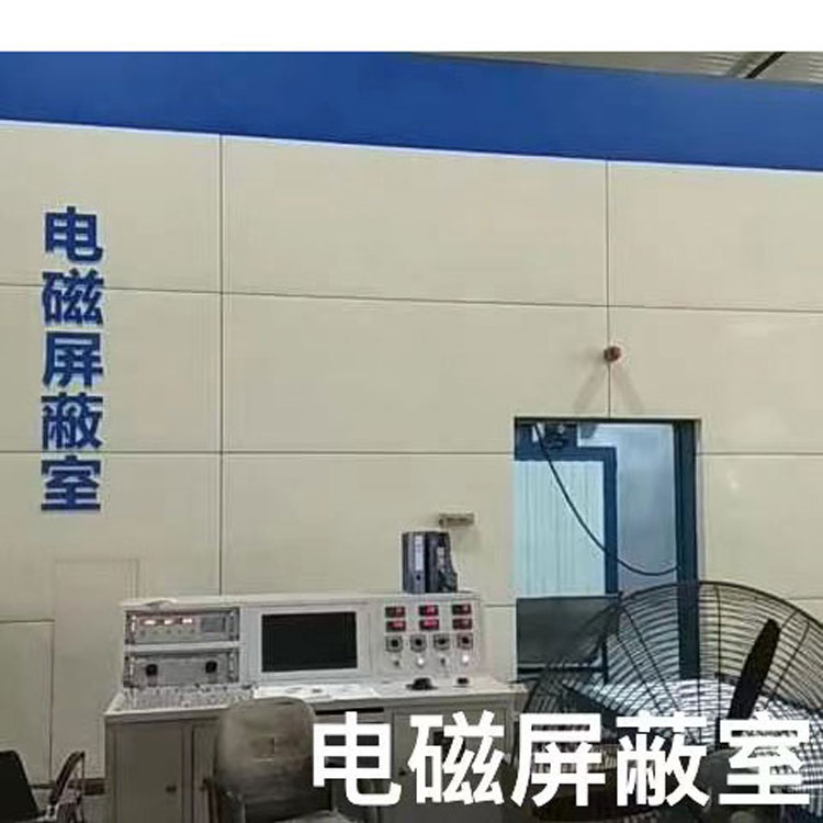
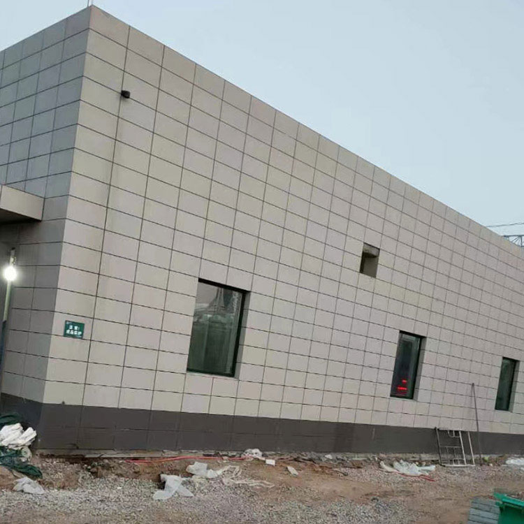
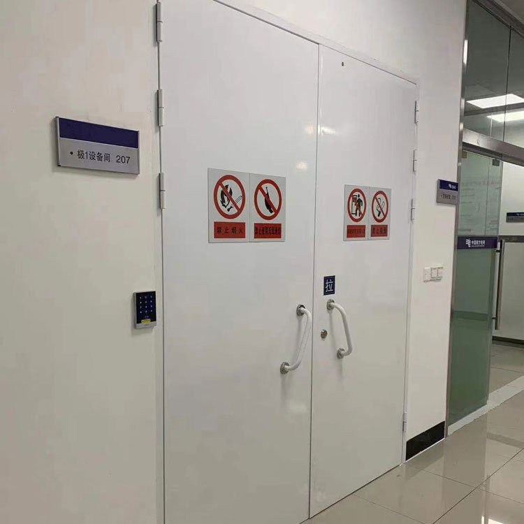
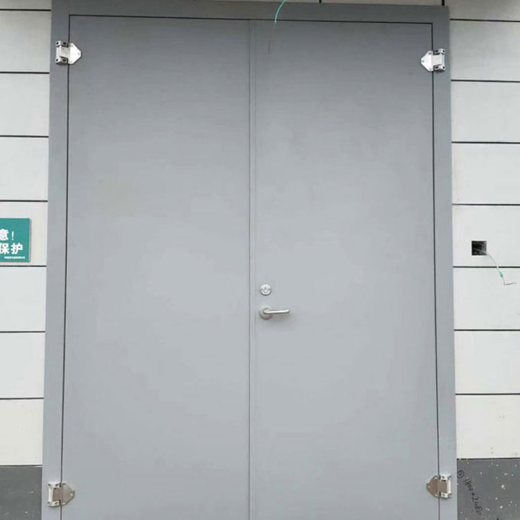
III. Structural Form:Sheet metal assembled shielding room
1. Housing: Four wallsThe panels are made of double-layered unit modules constructed from δ=1.5mm thick galvanized steel sheets (decorative-free for indoor wall), while the ground and ceiling are made into shielding modules using single-layer δ=1.5mm thick galvanized steel sheets. After electrostatic powder coating, they are assembled with M8 bolts, nuts, washers, and conductive pads.
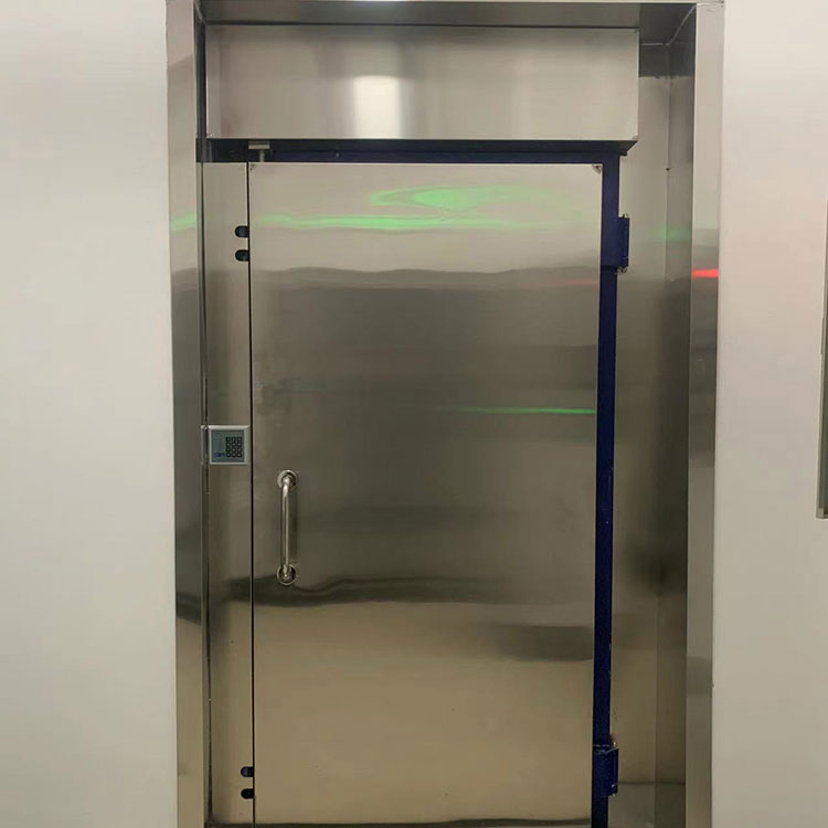
2. Electric Shielding DoorDoor Opening Size: 1900mm x 900mm; The shielding door employs a design that simultaneously presses the two rows of spring strips, the blade slot, and the copper plate of the door frame together to ensure the shielding effectiveness meets the requirements.
3 .Ventilation waveguide windowThe ventilation system of the shielding room employs a dedicated ventilation waveguide window, whose insertion loss corresponds to the specifications of the shielding room's equipment room. It consists of a waveguide bundle made up of many small waveguides, with the cross-sectional shape designed as hexagonal. Under the same insertion loss capability, the hexagonal waveguide has a larger passage area than the square waveguide, thereby expanding the ventilation area and reducing the resistance to air exchange.
The ventilation of the shielding room is achieved through an exhaust fan, utilizing cutoff waveguide windows. Pre-drilled holes for the installation of ventilation cutoff waveguide windows are provided at designated locations on the shielding shell. The waveguide windows are welded to the shell and a flanged decorative frame compatible with the exhaust fan is made. The indoor air outlet is decorated with aluminum alloy louvers.
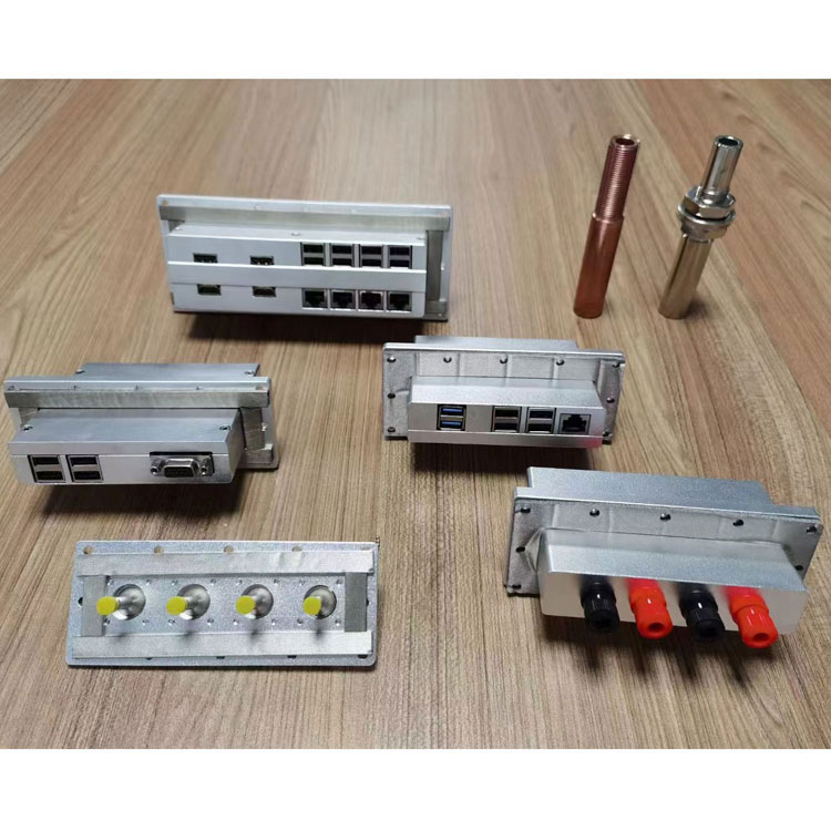
4 Filters
The filter is composed of three sections of high-frequency filters connected in series. Each section is well-shielded, and the adjacent sections are coupled with through-hole capacitors to achieve good characteristics. The waveguide connector (mounted with a hollow screw) is designed according to the principle of waveguide filters, preventing the reduction of shielding effectiveness by drilling holes in the shielding room walls, and it can effectively suppress electromagnetic waves below 3CM. This filter is a two-wire system filter; in principle, each pair of wiring should be connected to a filter, i.e., one for single-phase AC circuits. Filters are generally installed at the ceiling and side walls of the shielding room. To isolate the coupling effect between the input and output ends of the filter, the output lines should be brought into the shielding room, while the filter should be placed outside. To ensure the attenuation performance of the filter, there should be a reliable electrical contact between the filter housing and the metallic wall of the shielding room. The filter must be installed in a dry and ventilated area.
Installation sequence of the filter
Pre-drill holes at the filter installation location in the shielding room.
(b) Thread the waveguide connector through the hole and into the room, then secure the nut onto the shielding wall (copper mesh or steel plate) indoors.
(c) The outdoor power input is connected to the filter's wiring, while the indoor power is extracted from the waveguide connector and connected to the wiring. When wiring, the red wire corresponds to the phase line, and the yellow wire corresponds to the neutral line.
5. Grounding Equipment:Draw a 10 square grounding wire from the shielding room shell and connect it to the equipotential grounding rod.
6 Indoor Electrical Equipment:Distribution boxes, LED lighting lamps, multi-purpose outlets — To ensure stable operation of the shielding room and minimize malfunctions, electrical materials must be strictly selected from branded products that comply with national standards. The routing of cables through conduits and the arrangement of switches and outlets are customized according to customer requirements.
Interior decoration:Ceiling: Micro-perforated aluminum panel + Floor: Color steel plate + Gypsum board + Anti-static floor + Track