


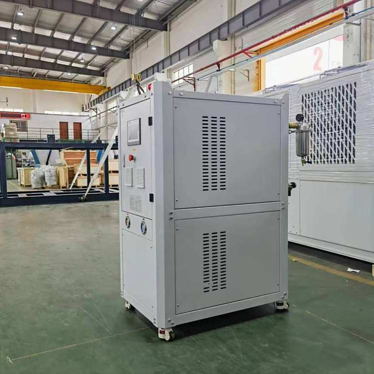


Temperature and Pressure Reducing Valve
The temperature and pressure reduction unit is a widely used steam energy parameter (pressure, temperature) conversion device and a heat recovery energy-saving device in modern industry for combined heat and power generation, centralized heating (or steam supply), and enterprises in light industry, electricity, chemicals, textiles, etc. in thermal engineering. Through this unit, the steam parameters provided by the user are reduced to the appropriate temperature and pressure required by the user, meeting their needs, and enabling substantial energy conservation and rational use of heat energy.
I. Working Principle
The temperature and pressure reducing device is used in power plants, industrial boilers, and thermal power plants, where it reduces the pressure and temperature of the incoming primary (new) steam, P1 and t1, to achieve the required values of secondary steam pressure, P2, and temperature, t2, as specified by the production process.
The temperature and pressure reduction unit, along with its configured thermal control cabinet, offers comprehensive measurement and execution control functions, widely used in power plants, petrochemicals, light industry, metallurgy, and urban heating and cooling systems.

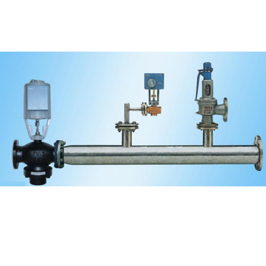
Section 2: Components of the Pressure and Temperature Reducing Valve
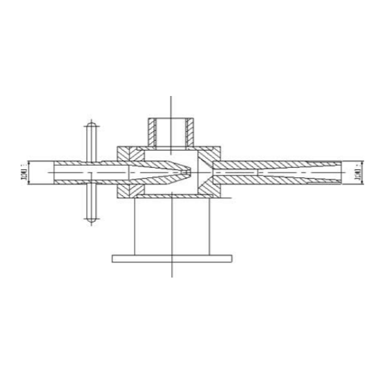
It consists of four main parts: a reducing and throttling valve, steam pipes, a reducing water pipe, and a thermal regulating device. This valve integrates three functions—reducing pressure, reducing temperature, and noise reduction—all within the valve body, completing them simultaneously. This design helps prevent premature damage to components caused by excessive temperature differences, thereby extending the valve's service life.
1. Steam Pipeline: The use of a reducing and throttling valve eliminates the separate water spray cooling pipeline in the original reducing and throttling unit, reducing the overall length by about half. This makes the structure compact, occupying less floor space, and cuts down on engineering investment. Safety valves, pressure gauges, and thermometers are installed on the pipeline to ensure safe operation of the unit.
2. Reduction Water System: Comprised of a water supply regulating valve, check valve, stop valve, and water supply piping. The throttling element of the water supply regulating valve is a cage-type sleeve or multi-stage throttling element, capable of withstanding high pressure differentials to prevent cavitation from high-pressure media passing through small gaps, thereby avoiding erosion damage to the valve seat and throttling elements, and reducing the leakage amount. The throttling holes are arranged linearly, and regulating valves of the same diameter offer different CV values for selection, ensuring precision and sensitivity in adjustment.
3. Thermal Control Device: Comprising of a control cabinet and an electric actuator. The control method is divided into two types based on order requirements: automatic (electronic调节instrument automatic control) and remote control. The automatic control cabinet includes: a temperature indicator, a pressure indicator, regulators, alarms, operators, etc. The electric actuators for the reducing and throttling valves come in two types—linear and angular stroke—available for selection during ordering. The steam pressure regulation utilizes a primary pressure transmitter to convert steam pressure fluctuations into 4-20m current signals. These signals are then transmitted to the electric actuator unit via a proportional integral controller to achieve pressure adjustment. The steam temperature regulation is similar, using a thermal resistance (thermocouple) to convert the temperature signal into a 4-20mA current signal. This signal is processed through a proportional integral derivative unit and an operator to send an electrical signal to the electric actuator, which drives the feedwater regulating valve to adjust the flow rate, thus reducing the temperature.
Section 3: Temperature and Pressure Reducing Valve Schematic

Section 4: Ordering Instructions
Please provide the following at the time of contract:
1. Export steam flow rate Q, steam pressure P, inlet temperature t1, outlet temperature t2.
2. Reduced temperature feed water pressure Pb, temperature tb.
3. Specify control method; (Dashboard control, DCS control, DCS monitoring)
4. Control Categories: Electric, Pneumatic
When selecting pneumatic actuators, it is also necessary to provide:
1) Acting Forms: Gas-actuated or Gas-sealed
2) Gas Source Pressure
3) Supply electrical valve positioner electrical signals.
Other special requirements shall be noted or a separate technical agreement shall be signed after agreement.
5. Note: Due to the varied parameters of the temperature reduction unit, in order to provide users with detailed and accurate schematics, the design and user units should provide comprehensive process parameters. Our company will design and provide schematics for each unit accordingly, for construction drawing design purposes, and also as an attachment to the contract.