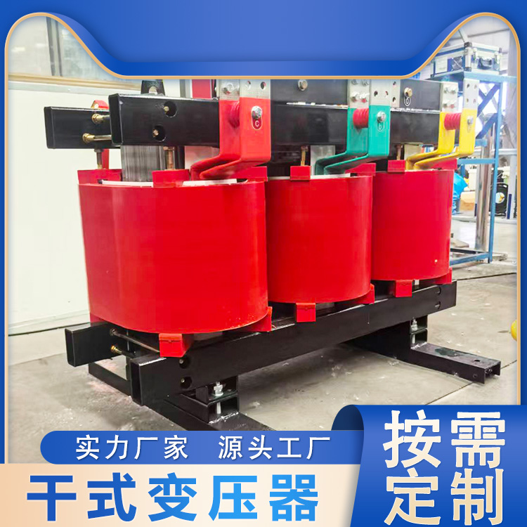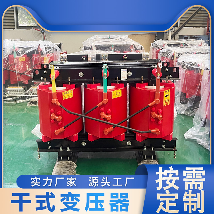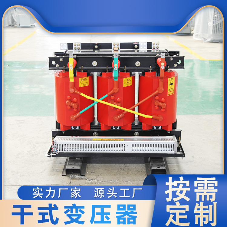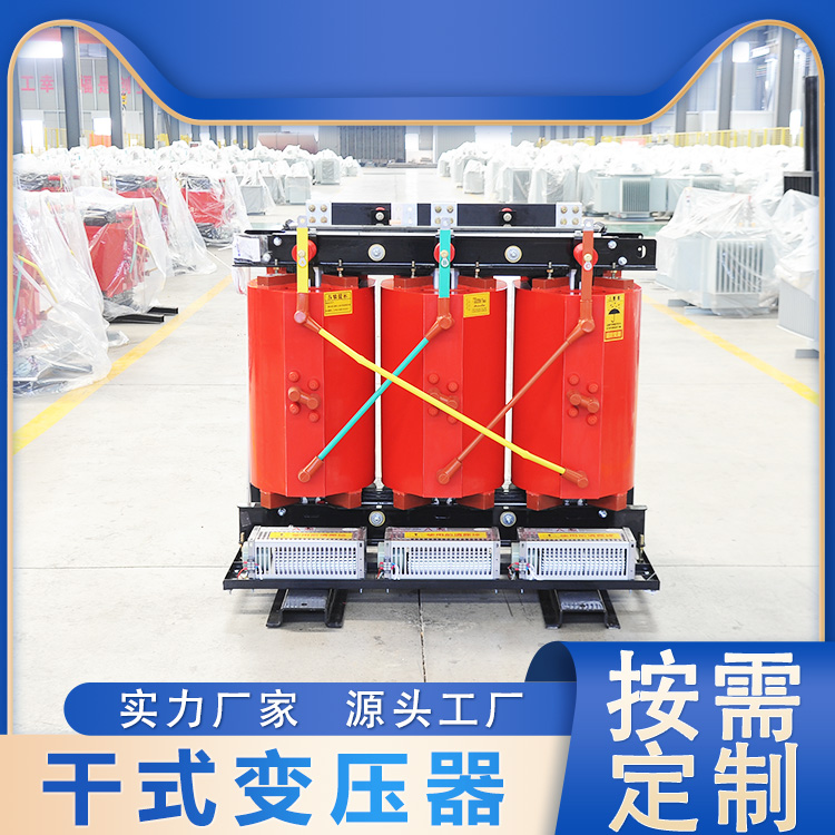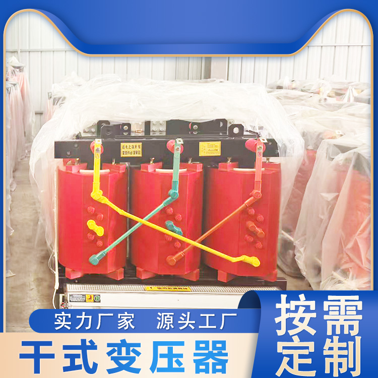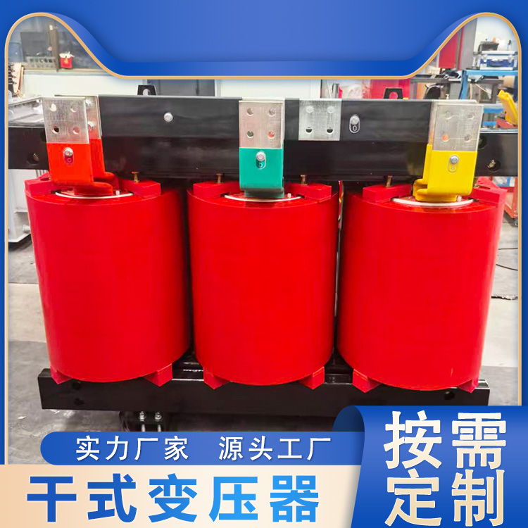


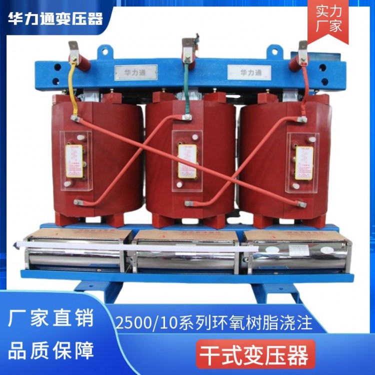
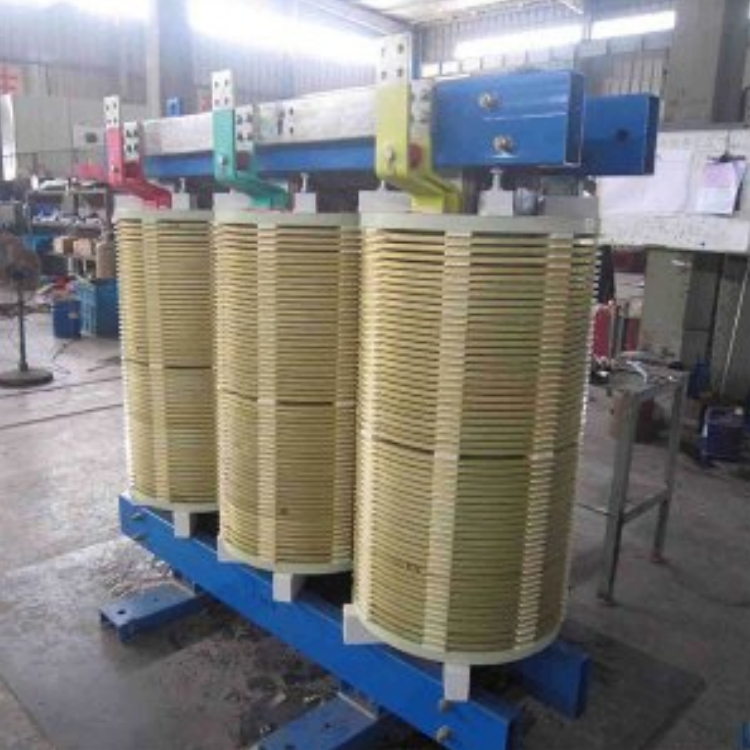


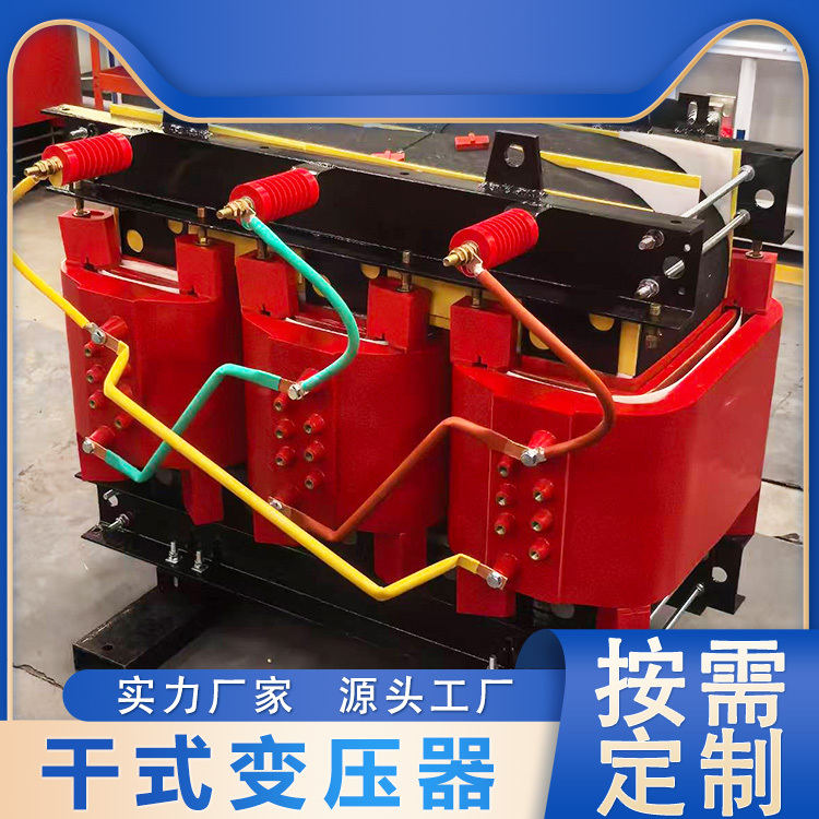


SC(B)10-30~2500/10 Series Epoxy Resin Casting Dry-Type Power Transformer
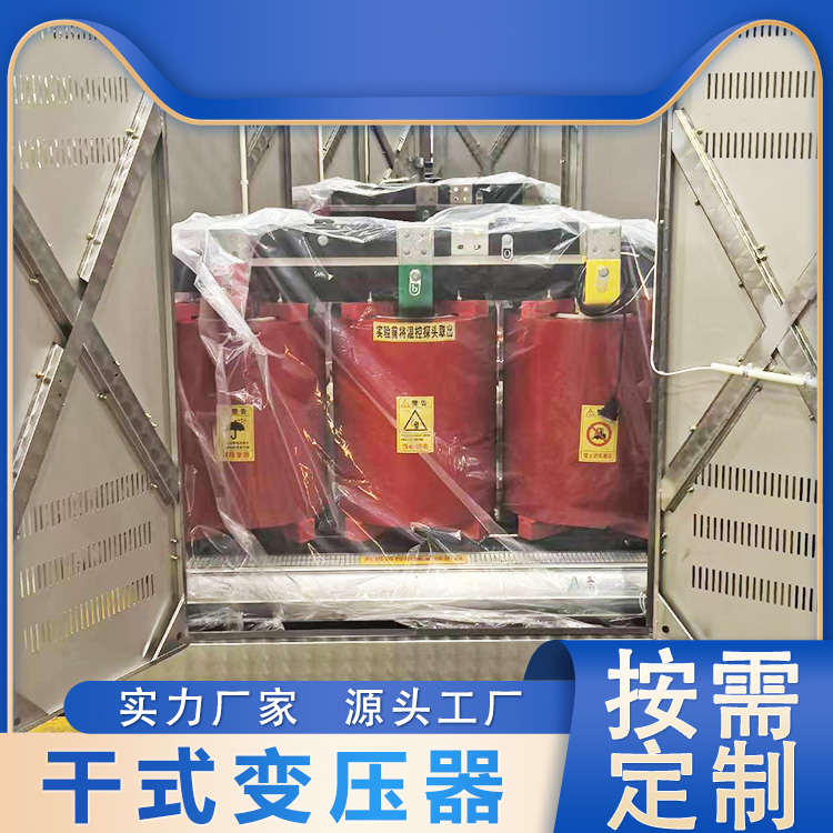
This series of epoxy resin casting dry-type transformer materials are selected with optimal formulations and produced using advanced production and testing equipment according to strict processes. The products feature high reliability and long service life. Depending on different usage environments, shells with varying protection levels can be configured or shells may not be used. Suitable for important or special environment locations such as high-rise buildings, commercial centers, airports, tunnels, chemical plants, nuclear power stations, and ships.
Feature Description:
Safety, fireproof, and non-polluting,可直接operated in the load center.
Utilizing German HTT technology, features include high mechanical strength, excellent short-circuit resistance, minimal partial discharge, good thermal stability, high reliability, and a long service life.
Low loss, low noise, significant energy-saving effect, maintenance-free.
Excellent heat dissipation, strong overload capacity, and can increase capacity operation when forced air-cooled.
Excellent moisture-proof performance, suitable for operation in high humidity and other harsh environments.
Equipped with a complete temperature monitoring and protection system. Utilizes an intelligent signal temperature control system that automatically monitors and巡回 displays the working temperatures of each three-phase winding. It can automatically start and stop the fan, and has features such as alarm and trip settings.
Compact, lightweight, minimal space required, and low installation costs.
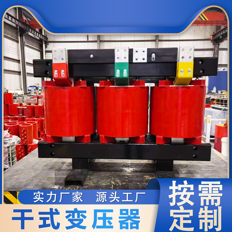
The core is made of cold-rolled silicon steel sheets, featuring a 45-degree stepped full斜seam structure. By utilizing a three-cut, two-punch core trimming process and a five-step stepwise shearing and lamination technique, the magnetic flux distribution at the seam is improved, reducing the vibration energy of the core. The core is subjected to a unified curing process and sealed with insulating resin on the surface, effectively lowering no-load losses, no-load current, and core noise.
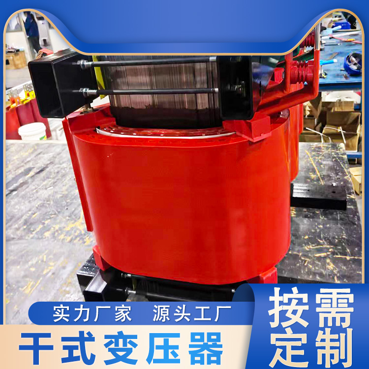
High-voltage coils are wound with wire insulated with F-grade material and internationally advanced insulation, with larger capacity coils featuring axial ventilation channels for heat dissipation. This design boasts excellent resistance to current surges, temperature fluctuations, cracking, and superior heat dissipation capabilities. Employing a multi-stage segmented cylinder structure, it has strong overvoltage withstand capacity and very low partial discharge levels. The coils are molded and vacuum dried before being cast, with the entire casting and curing process completed according to pre-programmed process curves. Precise process control ensures the coils are free of air bubbles and voids.
The low-voltage coil utilizes a foil structure, effectively addressing the issue of ampere-turn imbalance in coils with low voltage and high current, which typically use the wound type. The foil coils do not have axial turns or winding helix angles, thereby effectively eliminating the axial force on transformers during short circuits. This ensures that the current density within the coil can be freely adjusted along the axis according to the load distribution of the high-voltage coil, reducing radial forces during low-voltage sudden short circuits. The ends of the wound coils are sealed and cured with resin, preventing the entry of various foreign objects and moisture.

Nominal Capacity | Voltage Combinations | Connector group number | Short-circuit Impedance | No-load loss | Load loss | No-load current | Noise Level | Weight | ||
High-pressure | Tap | Low-pressure | ||||||||
125 | 6 | ±5% | 0.4 | Y yn0 | 4 | 480 | 1710 | 0.9 | 45 | 750 |
160 | 550 | 1860 | 0.9 | 45 | 900 | |||||
200 | 630 | 2210 | 0.8 | 46 | 1050 | |||||
250 | 730 | 2410 | 0.8 | 47 | 1280 | |||||
315 | 890 | 3040 | 0.7 | 47 | 1550 | |||||
400 | 990 | 3490 | 0.7 | 48 | 1700 | |||||
500 | 1170 | 4280 | 0.6 | 48 | 2150 | |||||
630 | 1350 | 5150 | 0.5 | 48 | 2400 | |||||
630 | 6 | 1300 | 5220 | 0.5 | 49 | 2450 | ||||
800 | 1530 | 6100 | 0.4 | 50 | 2950 | |||||
1000 | 1790 | 7130 | 0.4 | 51 | 3500 | |||||
1250 | 2110 | 8500 | 0.3 | 52 | 3900 | |||||
1600 | 2470 | 10290 | 0.3 | 53 | 4600 | |||||
2000 | 3350 | 12690 | 0.25 | 54 | 5500 | |||||
2500 | 4000 | 15080 | 0.25 | 54 | 6200 | |||||
Normal usage conditions are met when the following usage requirements are satisfied:
a. Altitude
Altitude not exceeding 1,000m.
b. Ambient Temperature
To High Temperature +40℃
ToHigh Average Daily Temperature +30℃
ToAverage Annual Mean Temperature +20℃
ToLow temperatures -30℃ (for outdoor transformers)
ToLow Temperature -5℃ (Suitable for Indoor Transformers)
c. Power supply voltage waveform
The waveform of the power voltage resembles a sine wave.
d. Symmetry of multi-phase power voltage