


Venturi Gas Water Mixing Heater Jet (Self-Controlled)


Structure and Principle
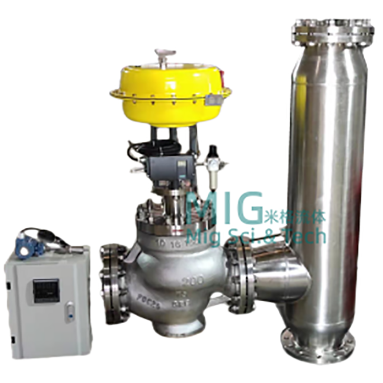
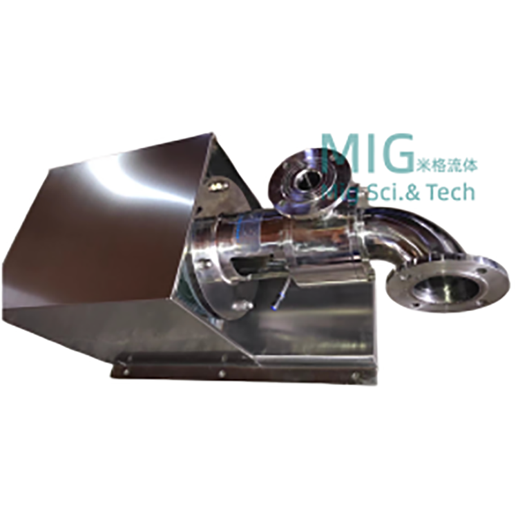
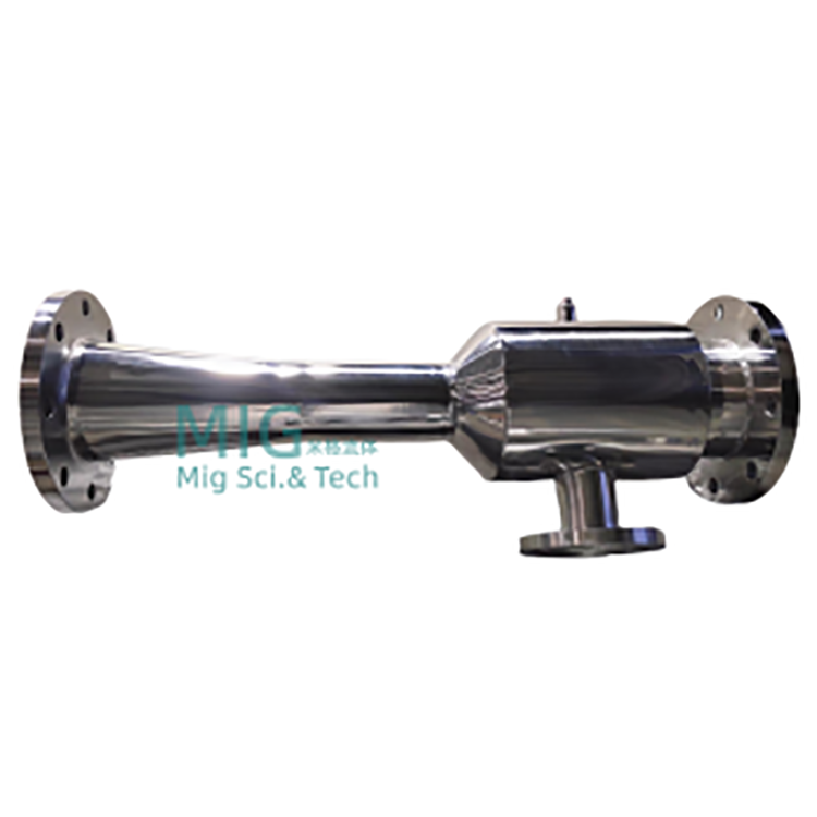
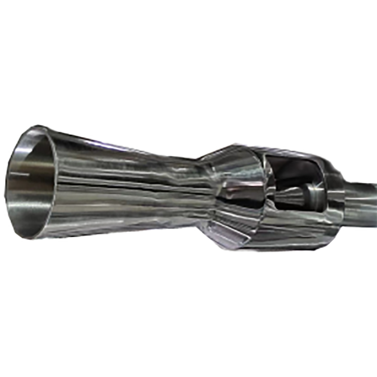
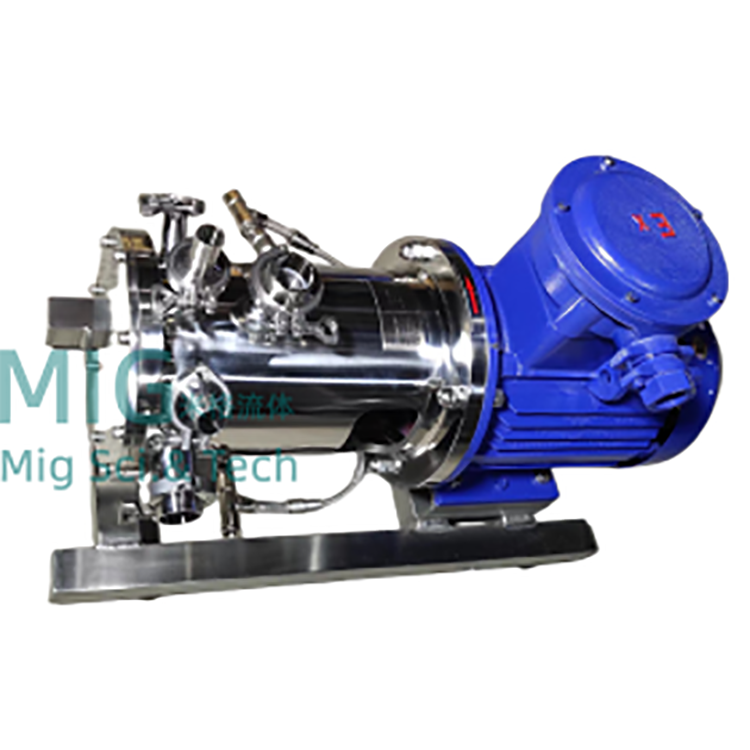
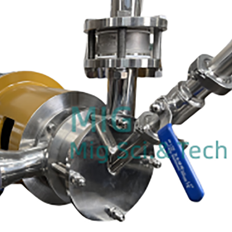
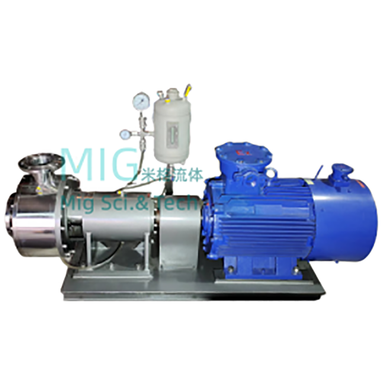
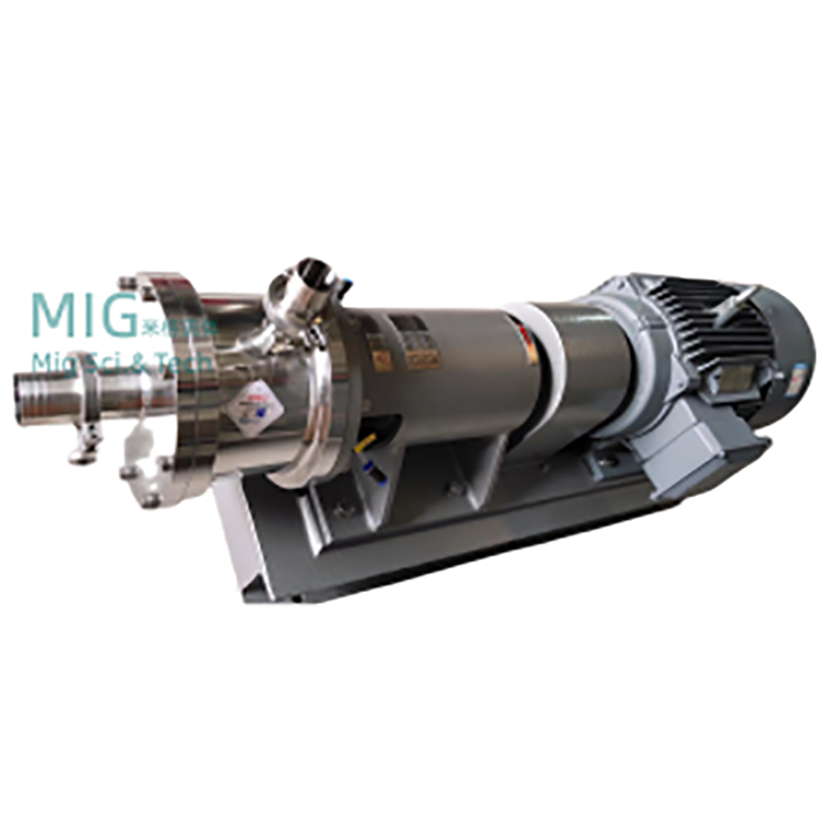
The heater is primarily composed of parts such as the nozzle, housing, grill, and gasket.
Steam passes laterally through the wall of the tube, as heated water flows through the Laval nozzle.
Small holes inject into the water, where they instantly and thoroughly mix with the high-speed flow to achieve water heating. Adjusting the steam side valve (manual or automatic valve) yields the desired temperature of hot water.
Job Characteristics
For open and closed systems, Tables I and II respectively list the relationship between different temperature differences and steam consumption under rated water inflow and steam pressure of 0.4MPa, for users to refer when selecting heaters and checking steam sources (note: 0.4MPa steam pressure is not necessarily the operating condition of the heater).
Open System Steam Consumption Gauge
Table I (Saturated Steam Pressure: 0.4 MPa) Unit: t/h
SQS | 4 | 6 | 8 | 10 | 12 | 16 | 20 | 24 | 32 | 40 | 48 | 64 | |
Rated Inflow Flow Rate | 1.2 | 2.5 | 4.5 | 7.0 | 10 | 16 | 25 | 35 | 60 | 105 | 165 | 260 | |
Temperature Difference for Heating (°C) | 20 | 0.039 | 0.081 | 0.146 | 0.228 | 0.325 | 0.520 | 0.813 | 1.138 | 1.951 | 3.145 | 5.366 | 8.455 |
40 | 0.081 | 0.188 | 0.303 | 0.471 | 0.672 | 1.076 | 1.681 | 2.353 | 4.034 | 7.057 | 11.092 | 17.475 | |
60 | 0.125 | 0.261 | 0.459 | 0.730 | 1.043 | 1.669 | 2.609 | 3.652 | 6.261 | 10.952 | 17.217 | 27.130 | |
80 | 0.173 | 0.360 | 0.649 | 1.009 | 1.441 | 2.306 | 3.603 | 5.045 | 8.649 | 15.135 | 23.784 | 37.477 | |
Steam Consumption Chart for Recirculation System
Table II (Saturated Steam Pressure: 0.4 MPa) Unit: t/h
SQS | 4 | 6 | 8 | 10 | 12 | 16 | 20 | 24 | 32 | 40 | 48 | 64 | |
Rated Inflow Flow Rate | 1.2 | 2.5 | 4.5 | 7.0 | 10 | 16 | 25 | 35 | 60 | 105 | 165 | 260 | |
Heating Temperature Difference (°C) | 70~95 | 0.054 | 0.112 | 0.201 | 0.312 | 0.446 | 0.714 | 1.116 | 1.562 | 2.687 | 4.687 | 7.366 | 9.204 |
70~110 | 0.088 | 0.183 | 0.330 | 0.514 | 0.734 | 1.174 | 1.830 | 2.569 | 4.404 | 7.706 | 12.116 | 19.083 | |
70~130 | 0.137 | 0.286 | 0.454 | 0.800 | 1.143 | 1.829 | 2.857 | 4.000 | 6.857 | 12.000 | 18.857 | 29.714 | |
Note: Steam pressure of 0.4 MPa is not necessarily the operating condition for Tables I and II. Please refer to the Installation and Usage Instructions on Page 3 for the operating conditions of this equipment.
The outlet water temperature can be controlled automatically or manually, simply by adjusting the steam side valve opening.
In high-temperature hot water heating systems, the heater should be installed on the outlet side of the water pump. In low-temperature hot water heating systems (outlet temperature ≤95℃), the heater can also be installed on the inlet side of the water pump.
Installation and Usage Instructions
Operating Conditions for This Equipment:
Safe Operating Conditions: Steam Pressure Entering the Heater: P0
SQS—4~SQS—24 P0≤1.6MPa
SQS—32~SQS—64 P0≤1.0MPa
Optimal operating conditions
SQS—4~SQS—24 P1+0.05≤P0≤0.6MPa
SQS—32~SQS—64 P1+0.05≤P0≤0.5MPa
Equation: P0Steam Working Pressure (MPa)
P1Inlet Pressure (MPa)
For SQS-32 to SQS-64 products in the circulating system, if the incoming water pressure is too high (not meeting P1+0.05≤P0Heaters should be installed on the suction side of the pump (under certain conditions), using a hot water circulating pump to ensure optimal operation.
In an open system, the incoming water pressure P1Should be ≥ 2.0 kg/cm²2When using superheated steam as the heat source, the heating should be done in sections.
Application Scope:
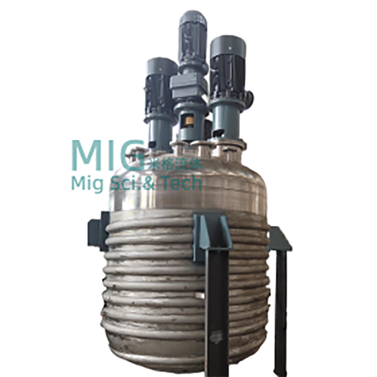
Used in hot water heating systems as heating equipment, replacing the original flat (indirect) heat exchangers.
Used for heating water in bathrooms, it supplies water to the tank, replacing the original high-noise, strong-vibration steam direct heating method (pipe bundle) in the original hot water tank.
Prepared soft water for oxygen scavenger preheating (thermal oxygen removal).
Installation Method: This equipment can be installed horizontally or vertically
In hot water heating systems, this heater can be installed on either the outlet or inlet side of the electric circulating pump when the power source is an electric pump. When the power source is a steam jet pump, the heater must be installed on the outlet side of the jet pump only.
In a hot water heating system powered by an electric pump, the installation condition of this heater on the inlet side of the pump:
The outlet water temperature of the heater must be below the boiling point of the water at the pump inlet pressure, i.e., it must not cause the water at the pump inlet to vaporize.
B. Must be below the working temperature permitted by the pump itself.
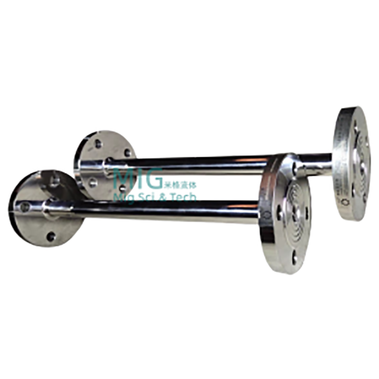
Installation Support for This Equipment:
1. SQS-4 to SQS-24 - Generally mounted on wall brackets or other metal supports.
2. SQS-32 to SQS-64 - Generally, a bracket or pier should be installed on the ground, with a load capacity considered at 500 kg.
Start/Stop
In an open system, first open the water side valve, then the steam valve; when stopping operation, first close the steam valve.
Car-side valve, then close the water-side valve.
In the recirculation system, the pipeline valves for water are generally kept open, only to start and stop the pump. Therefore, to invest
Upon startup, initiate the pump first, followed by the steam valve; upon shutdown, close the steam valve first, then stop the pump.
For hot water heating systems prone to frequent power outages, a high-temperature solenoid valve should be installed on the steam pipeline. When electricity is available, the solenoid valve remains in the open position; during power outages, the valve closes automatically, cutting off the steam supply and ensuring system safety.
(Ten) To prevent water from entering the steam piping, a check valve should be installed near the heater where the steam pipe is located.
(11) Water Pressure Loss: This heater is installed on the outlet side of the circulating pump. Without steam, its pressure loss is approximately 50KPa. When installed on the inlet side of the pump without steam, the pressure loss is around 0.15MPa. After adding steam with a temperature difference Δt ≥ 20℃, the pressure loss is zero.
(12) When using superheated steam as a heat source, to reduce noise, methods such as step-by-step heating, segmented heating, or steam temperature reduction can be employed.
(Thirteen) Upon initial operation, there may be slight water hammer, but it will automatically disappear shortly thereafter.