TL Type Air-Cooled Chiller

Product Overview
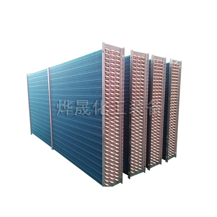
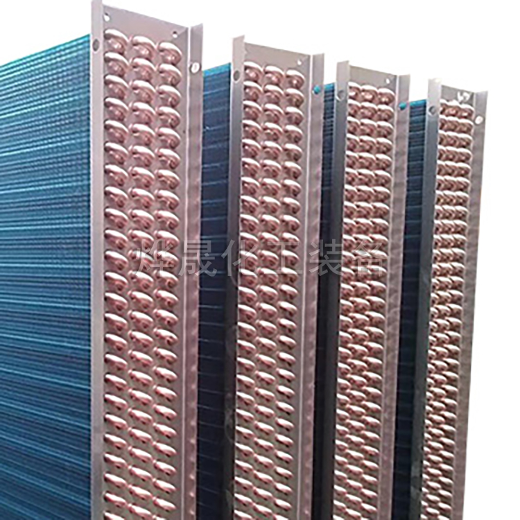
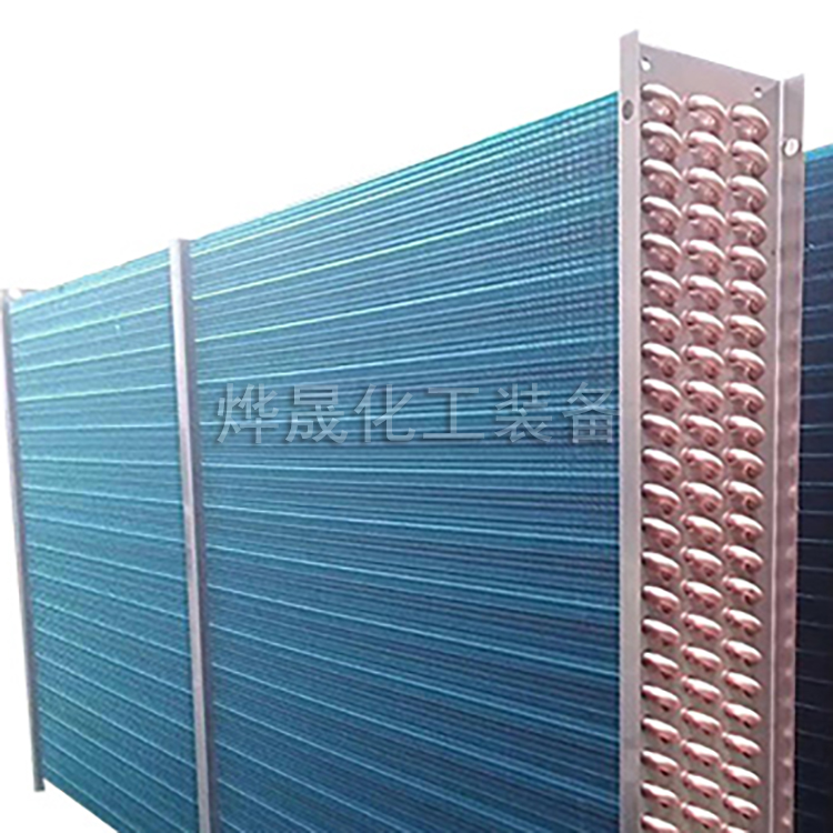
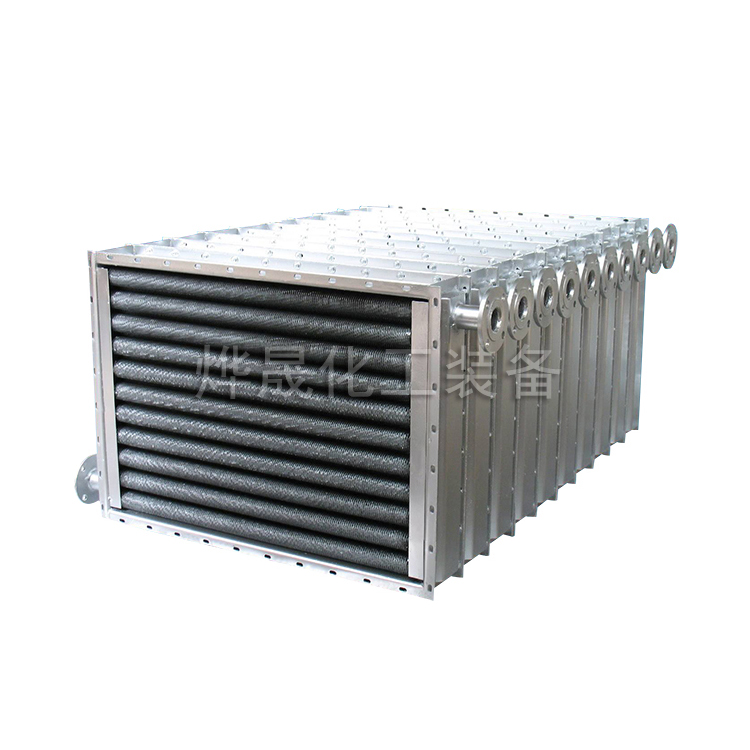
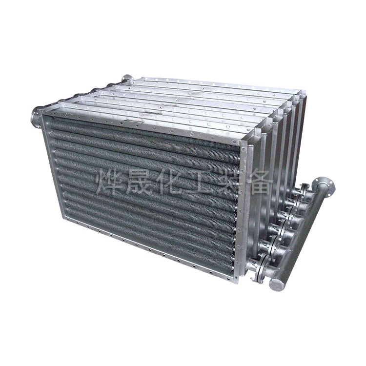
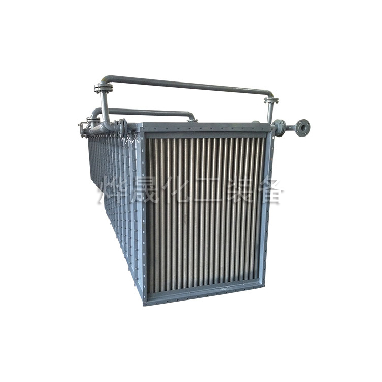
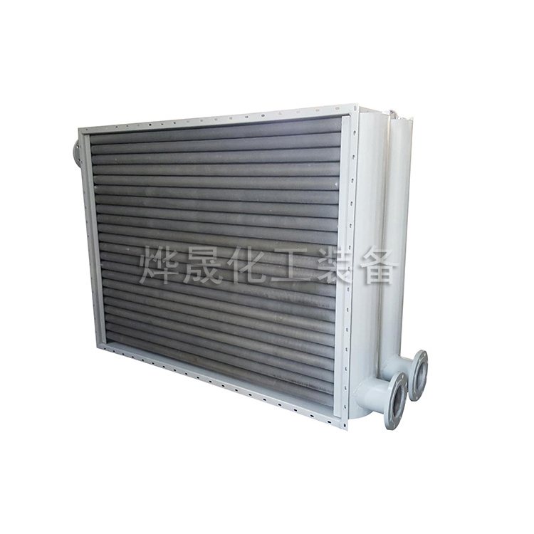
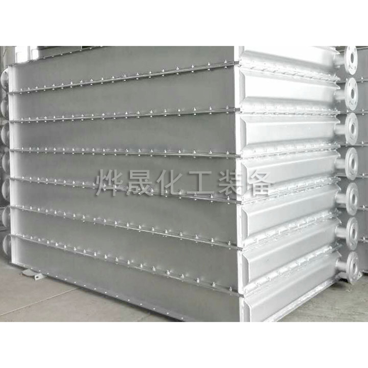
The TL type cooling coil is a copper tube through aluminum foil type cooling coil, utilizing mechanical expansion and arched corrugated double-flanged aluminum auxiliary plate structure. The mechanical expansion ensures tight contact between the copper tube and aluminum auxiliary plate, while the arched corrugations promote fluid turbulence, disrupt the boundary layer, and enhance the heat transfer coefficient. The structural design, combined with reasonable waterway length, tube spacing, and fin spacing, results in excellent heat transfer performance, low air resistance, compact structure, and light weight. It is widely applicable in air conditioning, cooling, dehumidification, and heating projects, serving as a suitable matching product for fresh air handling units and air processing units. It can also be connected to ducts for standalone use as either cooling or heating.
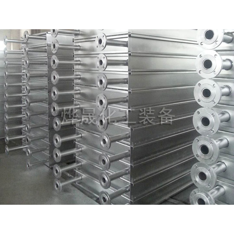
The copper tube welding utilizes low-temperature rapid brazing to ensure pressure resistance >1.2MPa.
The cooler table features a variety of pitch distances (2.5-3.6mm) and currently offers a complete range of species to meet the needs of different working conditions and various combinations.
From thermodynamic theory, it is known that for water-air heat exchangers, the large thermal resistance is on the air side. To increase the heat transfer coefficient, it is necessary to reduce the thermal resistance on the air side. An effective method is to utilize the boundary layer theory, increase the turbulent state of the air, i.e., increase the heat release coefficient on the air side. To this end, four auxiliary fin shapes have been designed.
●V-Type Aid ●V-Shape + Groove ●Sine Wave ●Sine Wave + Bridge
The four types of auxiliary sheets mentioned above can meet the different process requirements of various users.
TL type numbering method

Numbering Method
Example TL×4×24×1500 (Z) 3.0
TL Model
4 - Number of Rows N
24 - Number of Surface Tubes n
1500 - Surface Tube Length A
(Z) —— Airflow direction to the left (Y for right)
3.0 - Sheet spacing t=3.0
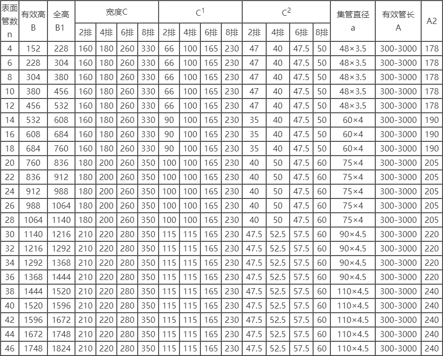
Technical specifications
Windward Area: F = A × B (m²) Heat Transfer Area: F = Fd · A · n · N (m²)
Single tube: Heat dissipation area per meter: Fd = 0.84 m² (pitch 3.0) Total water passage area: f = 1.767×10⁻⁴·n (m²)
Air Ventilation Ratio: Φ = Ff / Fy = 0.532 (calculated based on 3.0 spacing)
TL, TTS Type Outer Diameter Gauge (suitable for 2, 4, 6, 8 rows of pipe) - Unit of Measurement (mm)