


Model Description:
GB/T 7253-1987 and JB 9681-1999 Standards (Old Models):
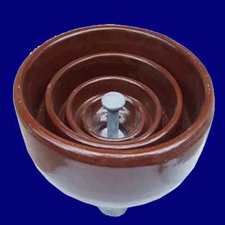
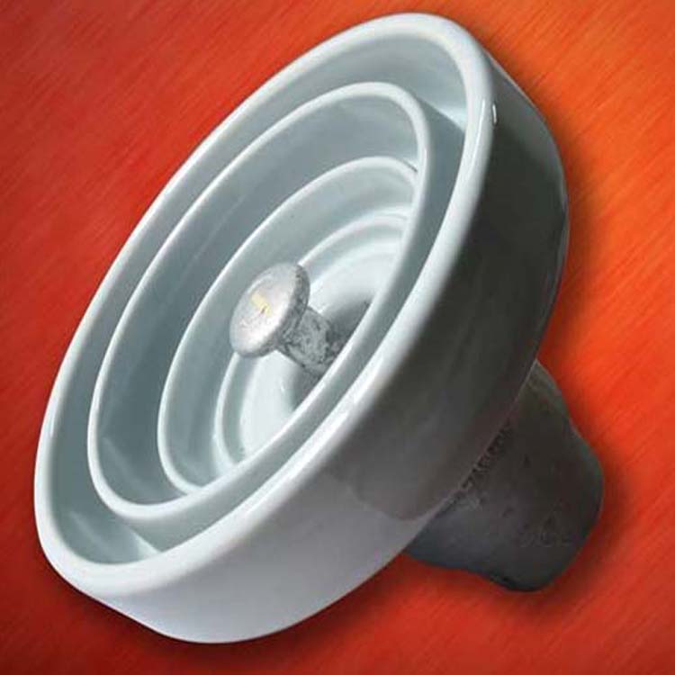
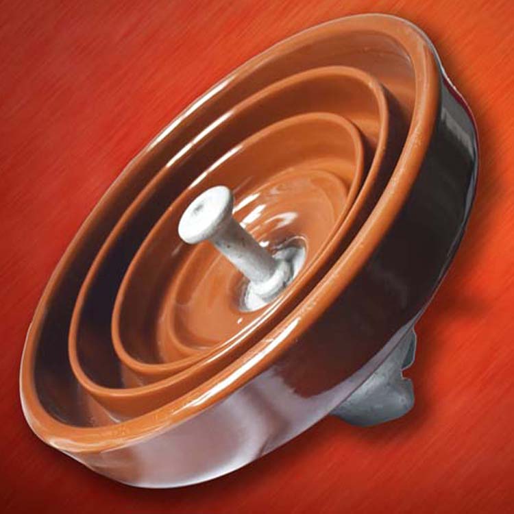
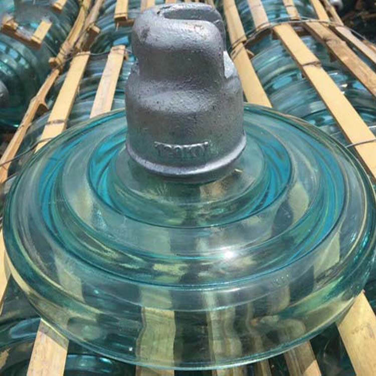
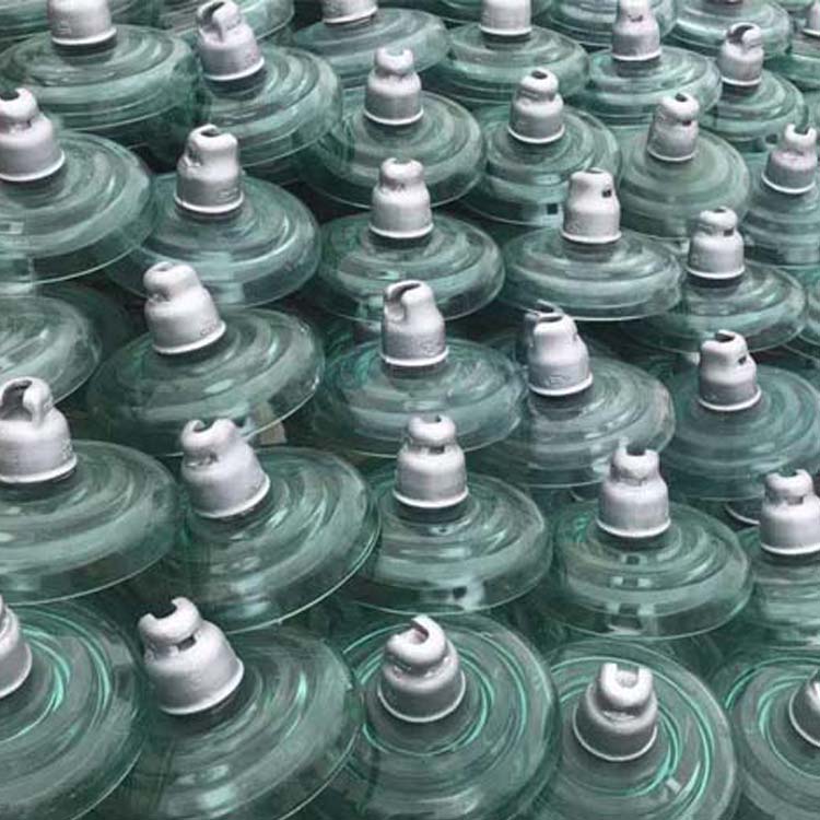
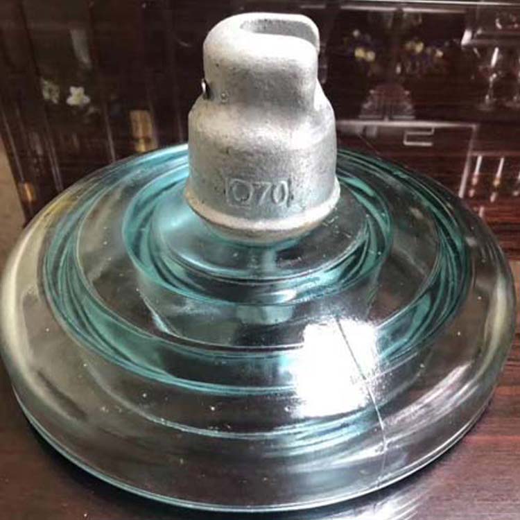
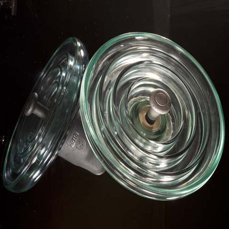
XP - Standard Type Disk Shaped Suspended Porcelain Insulator
XWP - Non-stick Dish-shaped Suspendable Porcelain Insulator
XHP - Spherical Cap Insulator with Anti-Fouling Dish for Overhead Suspension
XMP - Hat-shaped, Oil-Repelling, Disc-Type Suspended Ceramic Insulator
Numbers 1, 2, 3... are the design sequence numbers.
The number following “—” represents the rated mechanical and electrical breakdown load value, in kN.
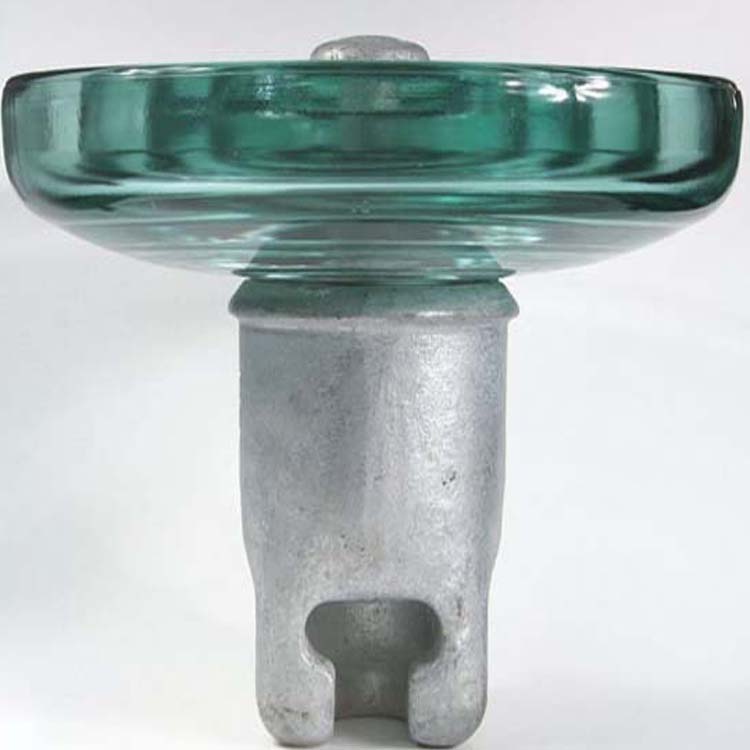
The "C" following the kN value denotes a slot-type connection structure, the "T" indicates a ball-joint cap-flange connection structure, and the ball-joint structure is not represented.
GB/T 7253-2005 Standard Specification (New Model):
U - Suspended Insulator
The number following "U" indicates the specified mechanical or mechanical failure load value, in kN.
B or C denotes ball joint or groove connection.
S or L denotes short or long structure height, M represents medium-long, and EL indicates extra-long.
P indicates the large爬距.
Note: The naming method for insulator designations in the bidding documents of the State Grid Corporation is as follows:
1. U70B/146: U—Suspended type, 70kN, B—Bushing connection, Standard type, 146—Structure height
2. U100BP/155D: U—Suspended, 100kN, B—Bushing-type connection, P—Corrosion-resistant, 155—Structural height, D—Double canopy
3. U160BP/170T: U-hanging, 160kN, B-bushing type connection, P-corrosion resistant, 170-structure height, T-triangle canopy
4. U70C(N)/200: U-hanging type, 70kN, C-slot type connection, CN-tension type, ground wire insulator.