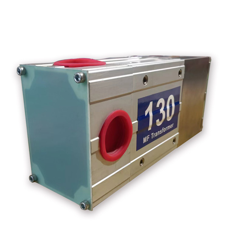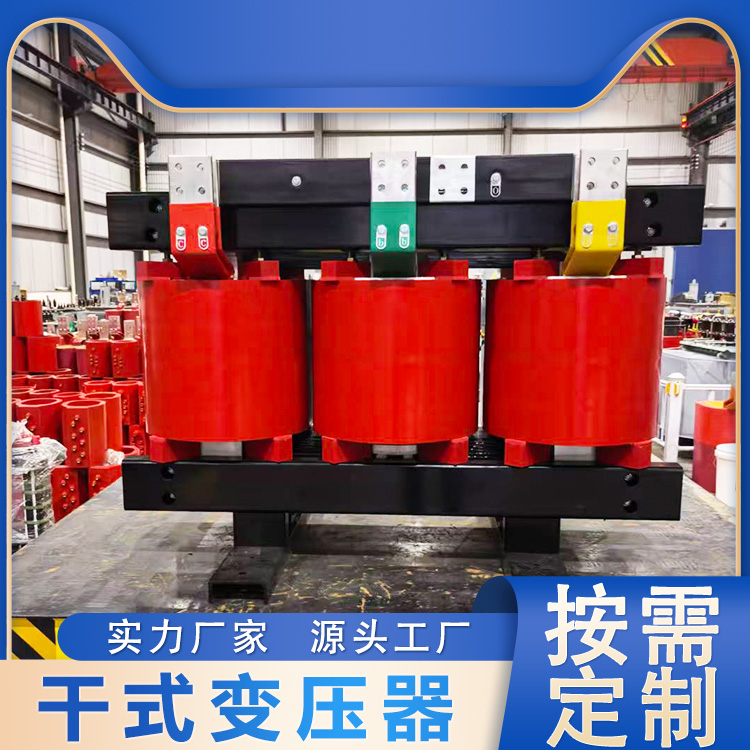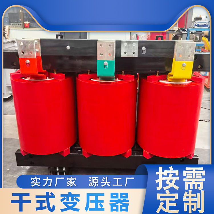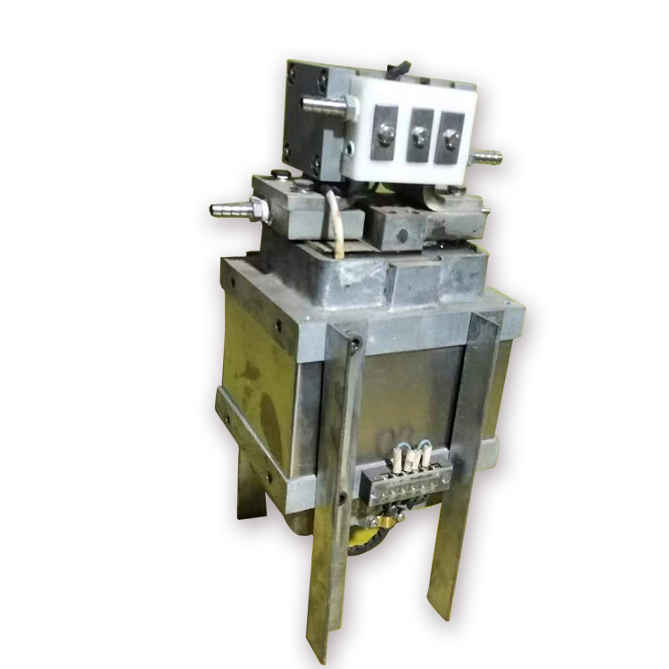

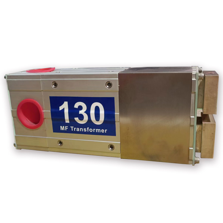


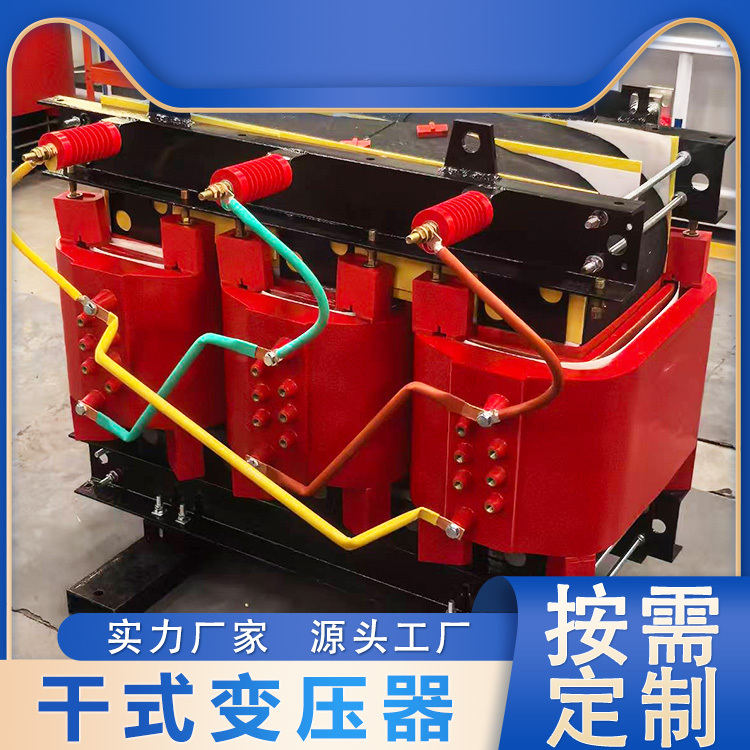


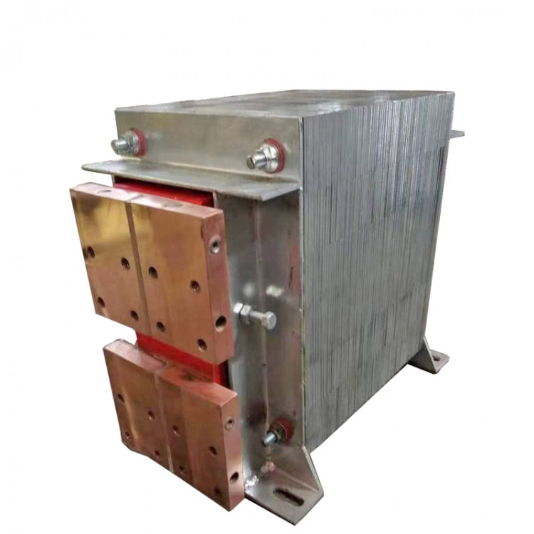
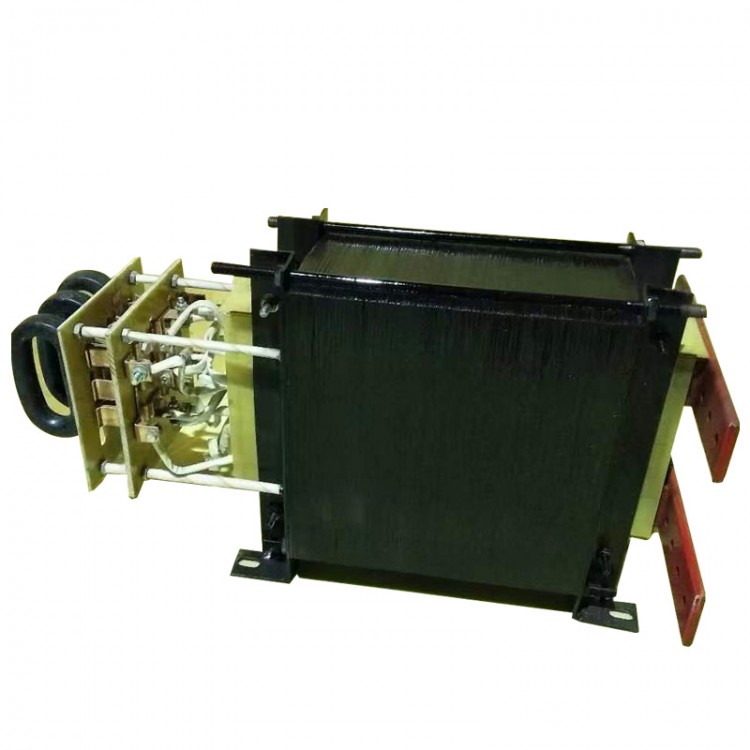
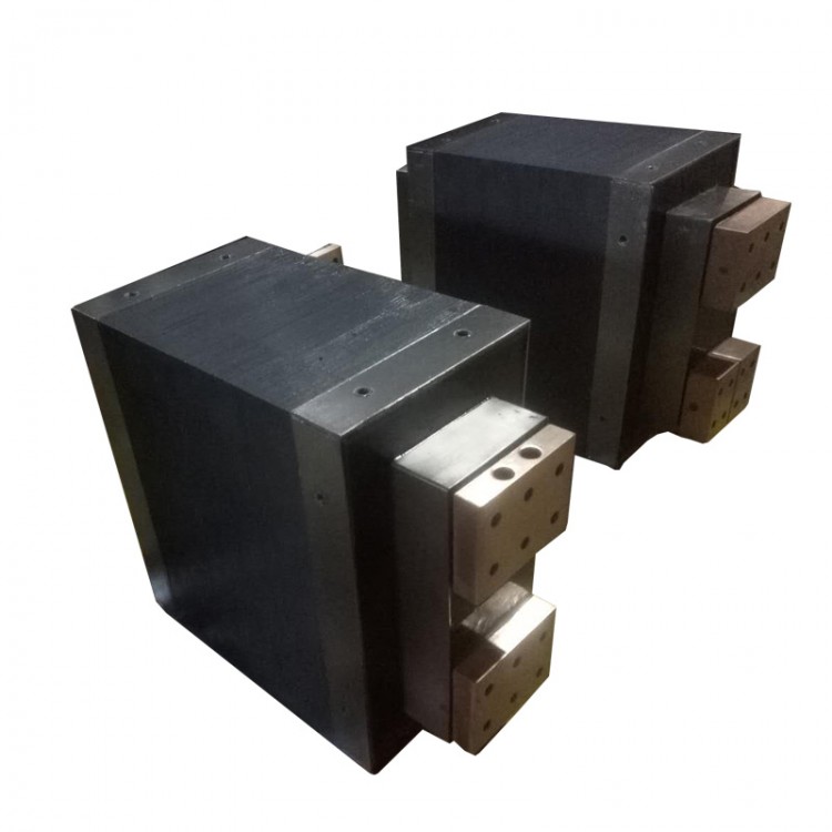
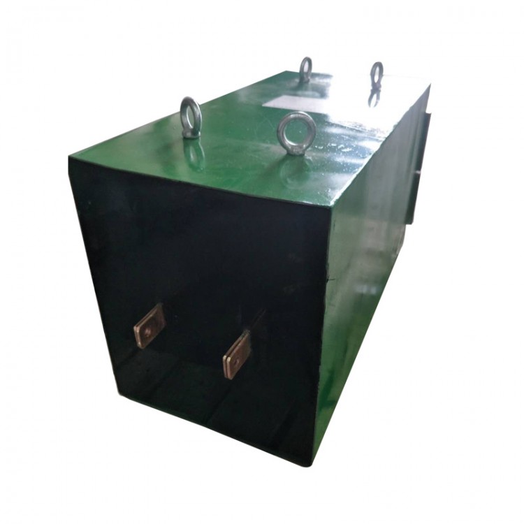
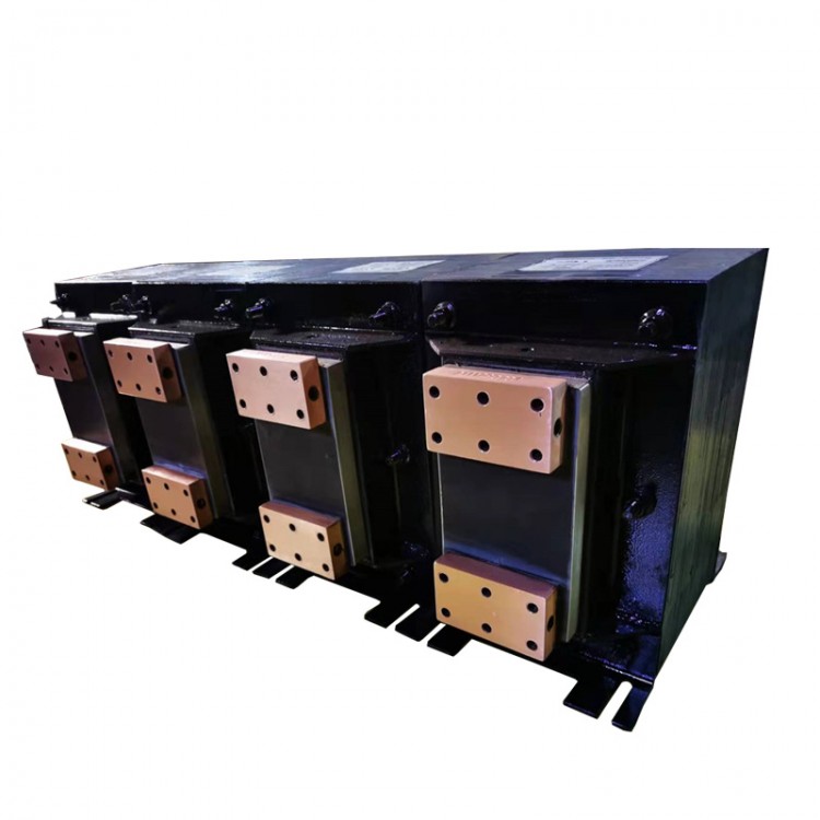
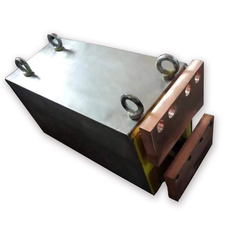
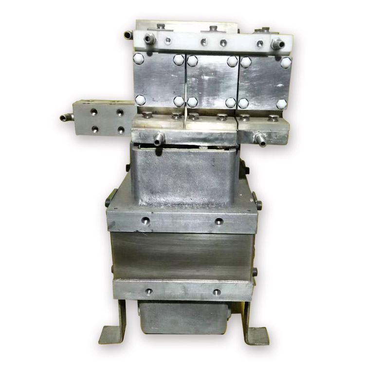
The medium-frequency welding transformer is made by combining ferrite high-permeability silicon steel sheets and then casting them with epoxy resin, significantly reducing the transformer's losses. Current measurement is conducted using sensors in the secondary circuit. The primary assembly features a temperature-sensing switch, while the secondary assembly includes a rectifier set. Any coil and rectifying element is equipped with water-cooled heat dissipation. This greatly reduces the weight of the core material.
The medium-frequency inverter is a critical power drive component of the equipment. It converts three-phase 50/60Hz 380V AC input into a high-voltage DC power source, which is connected to capacitors for filtering. Subsequently, the inverter outputs an appropriate 1KHz square wave based on the control input settings and feedback current. This is then used to generate low voltage through a medium-frequency welding transformer for the welding process. Additionally, the inverter box is equipped with an exhaust fan for forced air cooling of the inverter, ensuring safe operation.
Compared to traditional welding power sources, the following advantages are offered:
The system has enhanced adaptability to voltage fluctuations and drops in the power grid. A portion is stored and supplied to the load by the inverter, replacing the direct supply from the grid. It saves energy, improves power factor, and reduces processing costs. It can reduce interference in a large secondary circuit area. The welding current is DC, and it will not affect welding when there is induced (magnetic) material in the secondary winding. It offers more precise, quick, and accurate parameter analysis. It can prevent damage caused by the wave interference to the power grid induced by the thyristor system.