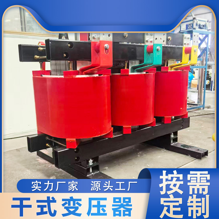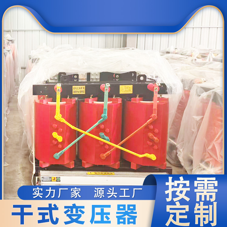


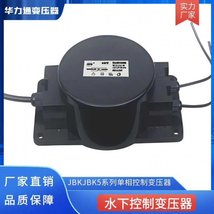


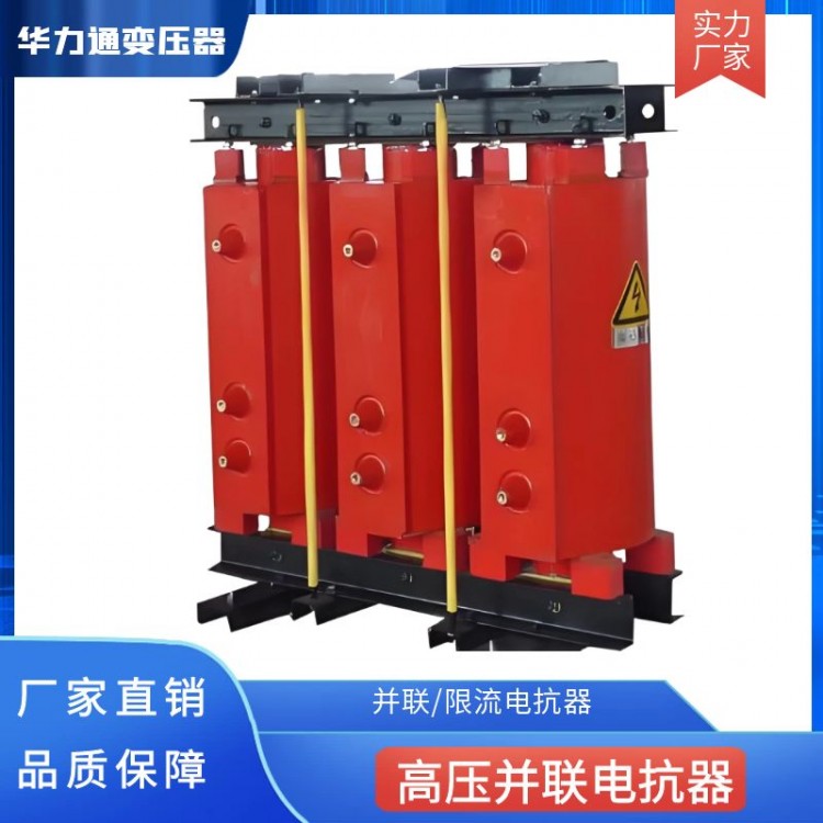
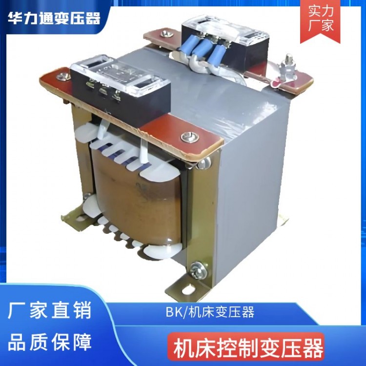
I. Overview and Application
The BK, JBKJBK5 series single-phase control transformers are produced by our company over the years using selected materials and advanced technology. They can penetrate deep into the load center. They are mainly used for various machine tool signal indications, control buttons, and safety operation circuits with AC 50-60Hz and voltages not exceeding 1500V. The distribution of various input and output voltages, connection groups, and tap line group capacities of the product can all be carefully designed and manufactured according to customer requirements. They also offer additional advantages such as fire resistance, moisture resistance, safety, energy savings, and convenient maintenance.
Two, Product Performance
Name: BK, JBK JBK5 Control Transformer
Model: BK, JBK5 (50VA-5000VA)
Input Voltage: Single-phase: 110V, 220V, 380V, 450V (Voltage can be customized by customer)
Output Voltage: Single-phase: 6.3V, 12V, 24V, 48V, 100V, 110V, 120V, 220V, 230V (Voltage can be customized by customer)
Efficiency: 95%
Waveform Distortion: No additional waveform distortion
Protection: Overcurrent protection, can operate continuously unattended
Insulation Resistance: ≥50MΩ
Electrical Strength: No breakdown or flashover under 2500V AC sine wave for 1 minute
Overload Capacity: Twice the rated current, maintained for 1 minute
Environmental Temperature: -15 to +40°C
Relative Humidity: <90%
Temperature Rise: 155°C (including ambient temperature)
Voltage Resistance: 2500V without breakdown
Insulation Class: F Class
Noise: <60db (one meter away)
Size Chart of JBK Series Control Transformers
| Project dimensions and capacity | max | max | max | Pilot Hole Spacing | Installation Holes | Stand Foot Thickness | Weight (KG) | |
| 40-63 | 83 | 85 | 89 | 56+-0.4 | 46+-2.5 | 4.8*9 | 1 | 1.3 1.9 |
| 100 | 86 | 105 | 94 | 64+-0.4 | 62+-2.5 | |||
| 160 | 98 | 105 | 109 | 84+-0.4 | 71+-3 | 5.8*11 | 1.5 | 2.6 3.6 |
| 250 | 98 | 120 | 109 | 84+-0.4 | 85+-3 | |||
| 400 | 122 | 102 | 125 | 90+-0.4 | 85+-2 | 5.8*9 | 2 | 5.0 7.5 |
| 630 | 152 | 112 | 150 | 122+-0.5 | 90+-3.5 | 7*13 | ||
| 1000 | 160 | 210 | 151 | 126+-2 | 152+-2 | 7*12 | 3 | 11 16 |
| 1600 | 184 | 235 | 163 | 146+-3.5 | 176+-3.5 | |||
| 2500 | 210 | 265 | 171 | 174+-3.5 | 200+-3.5 | 4 | 22 | |
Product dimensions listed above are for reference only; changes may occur without prior notice. Please understand!
Note: The installation site must not have significant evaporation of gases that adversely affect transformer insulation, chemical deposits, dust, dirt, and other explosive and corrosive media.
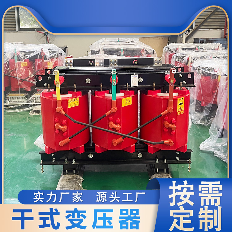
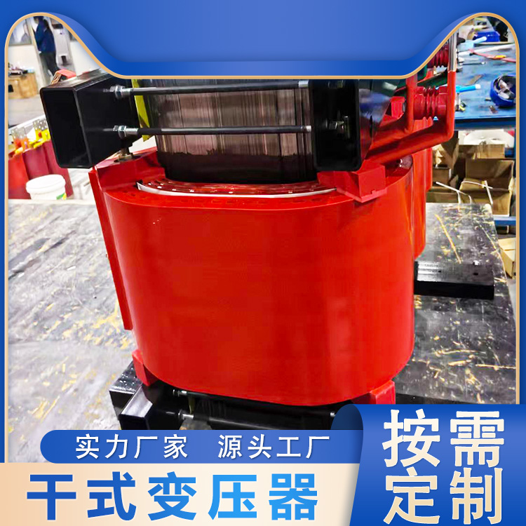
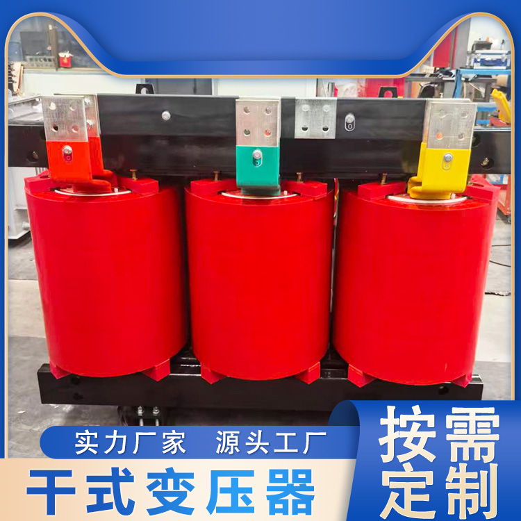
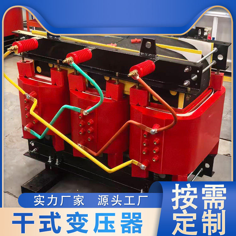
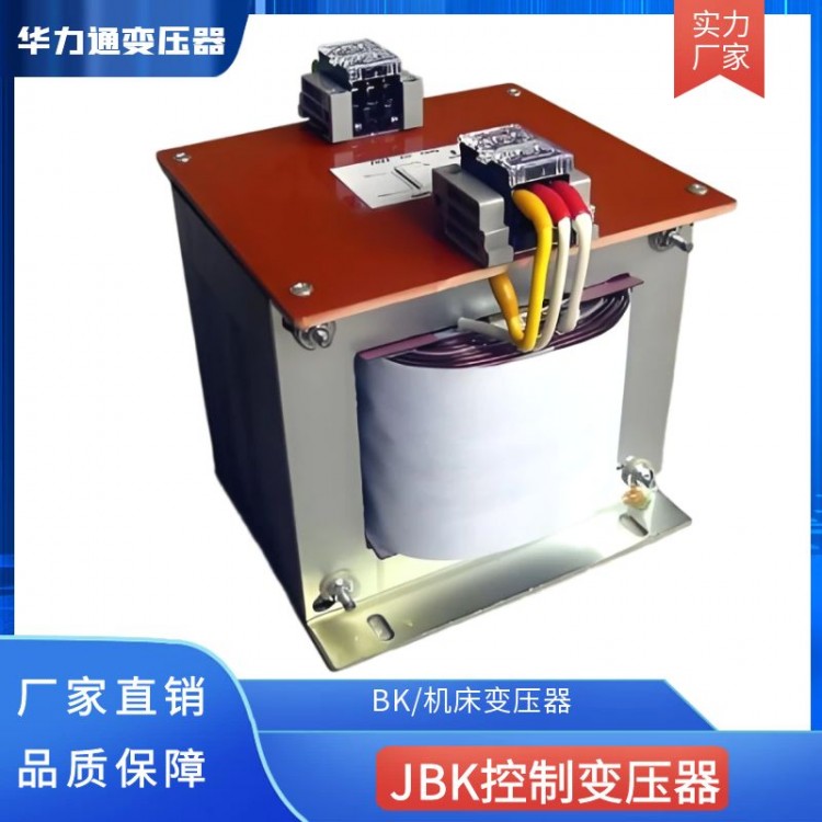
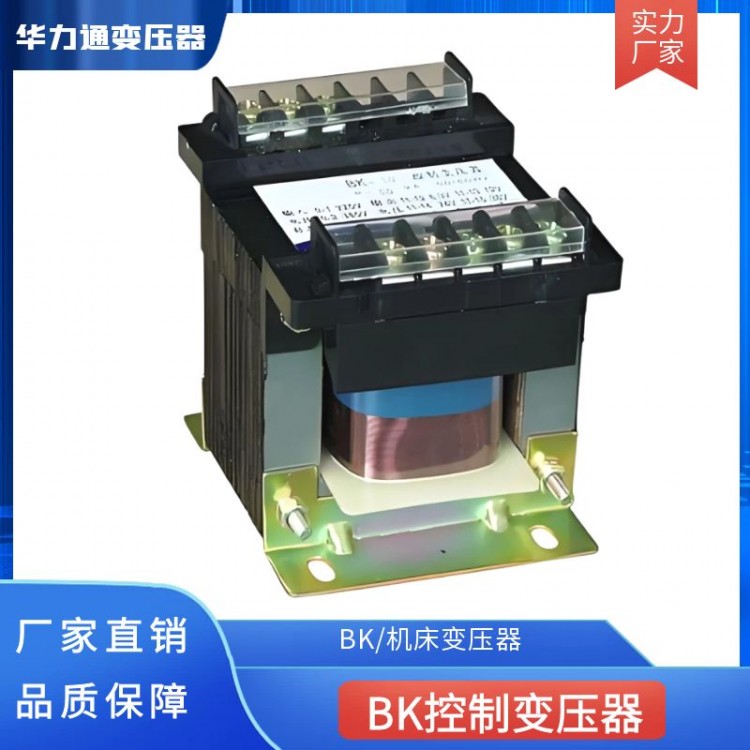
Structure and Features
BK Transformers can be categorized by structure into shell type, and by installation method into vertical type.。
■Model and Specifications
| Input Voltage | Output Voltage | Model and Specifications | Dimensions | Pilot hole spacing | Mounting hole | ||
| 220V ±10% 380V ±10% | 6V 12V 24V 36V 110V 127V 220V 380V Special voltages available for customization | BK-25VA | 80 | 75 | 90 | 65×49 | 5×9 |
| BK-50VA | 86 | 86 | 96 | 71×58 | 5×12 | ||
| BK-100VA | 98 | 89 | 108 | 83×64 | 6×12 | ||
| BK-150VA | 108 | 100 | 108 | 87×72 | 6×12 | ||
| BK-200VA | 108 | 110 | 108 | 87×83 | 6×11.5 | ||
| BK-250VA | 120 | 113 | 130 | 94×85 | 9×11.5 | ||
| BK-300VA | 116 | 121 | 135 | 97×95 | 9×11.5 | ||
| BK-400VA | 133 | 138 | 150 | 109×100 | 9×11.5 | ||
| BK-500VA | 133 | 148 | 150 | 109×113 | 9×11.5 | ||
| BK-700VA | 146 | 155 | 160 | 123×115 | 9×11.5 | ||
| BK-1000VA | 146 | 177 | 165 | 123×135 | 9×11.5 | ||
| BK-1500VA | 171 | 200 | 190 | 145×135 | 9×11.5 | ||
| BK-2000VA | 180 | 230 | 210 | 145×160 | 9×11.5 | ||
| BK-2500VA | 225 | 240 | 225 | 169×175 | 9×11.5 | ||
| BK-3000VA | 225 | 240 | 225 | 169×175 | 9×12.5 | ||
| BK-5000VA | 283 | 265 | 270 | 215×180 | 11×13.5 | ||
■ Usage Instructions
| 1. Surrounding air temperature ranges from -25℃ to +40℃, with a 24-hour average not exceeding +35℃. 2. Installation location altitude not exceeding 2,000 meters. 3. Relative humidity should not exceed 50% at an air temperature of +40°C, with higher relative humidity permissible at lower temperatures. The average humidity during the wet month is 90%, with a monthly average low temperature of +25°C, considering condensation on the product surface due to temperature changes. 4. No areas of severe vibration or shock. 5. Areas not susceptible to rain or snow. 6. The voltage waveform is approximately sinusoidal. | ■ NotePlease specify: Model, Capacity, Input Voltage, Output Voltage; (To be specified upon order) Friendly Reminder: Special voltages available for customization |