


Product Overview
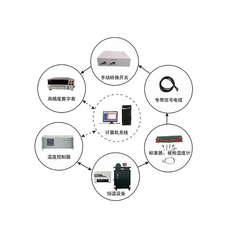
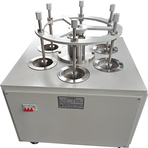
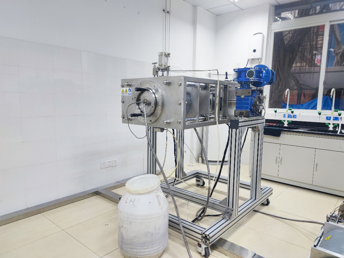
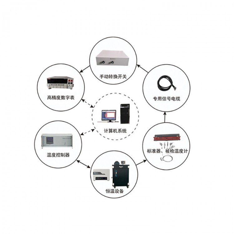
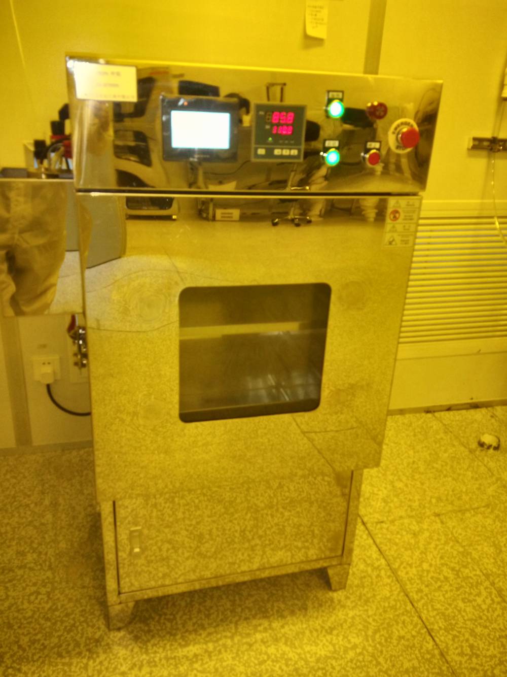
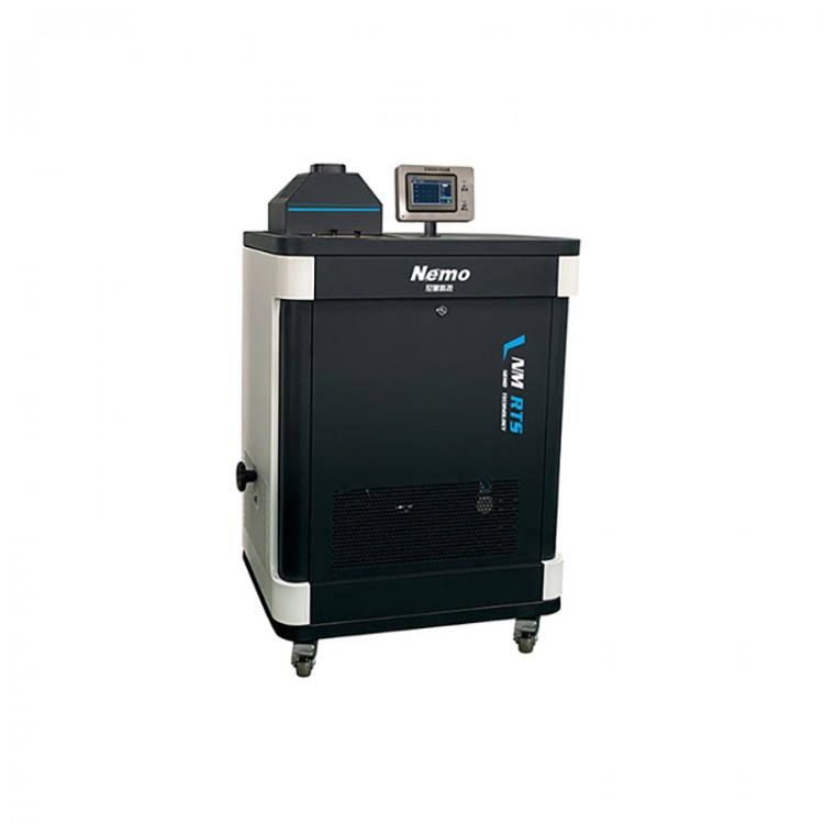
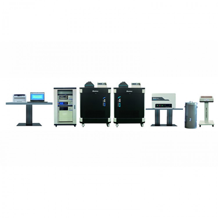
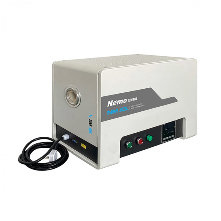
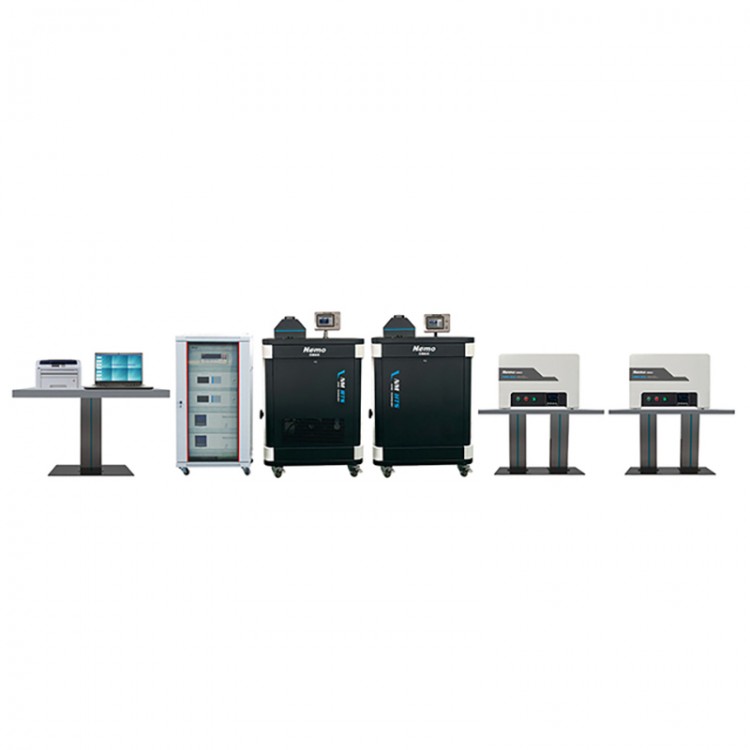
The NM-01S Thermocouple Resistance Manual Verification System consists of a manual changeover switch, high-precision digital meter, special cable signal lines, verification furnace, intelligent precision temperature control device, water (oil) tank, standard instruments, and an ice point instrument. Users can select different constant temperature equipment and standard instruments according to the temperature range of the sensor to be verified. Equipped with a computer, communication card, and corresponding verification software, the system can automatically control the temperature of constant temperature equipment during the verification process, read digital meter values, process data, and generate and print tables, forming a semi-automatic verification system.
Manual switch for multi-channel signal switching of the inspected and standard as well as reference sensor signals, featuring a lead switching function during three-wire resistance verification.
Special cable signal lines are for manual switches and sensor connection lines, used for connecting standardizers, reference terminal compensation sensors, and tested sensors.
Thermocouple and Resistance Thermometer Calibration System Configuration Sheet (Single Furnace, Double Furnace/Group Furnace, Manual)
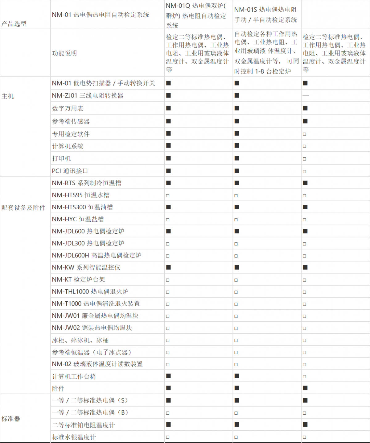
■ Standard Equipment
□ Indicates optional equipment
No equipment required.
Note: 1. The lower temperature limit of the low-temperature tank is selectable at -100°C, -80°C, -60°C, -40°C, -30°C, -10°C, and 0°C.
2. Standard gauges are selected based on the model and accuracy grade of the sensor to be inspected.
3. Optional digital multimeters: Keithley 2000/2010/2002, Agilent 34401A/34420A, etc.
4. Optional multi-channel scanners, available with 8 or 10 inspection channels