


Structural components for on-site load tests should be symbolic and ideally located at positions with significant loading and where there is a lack of support. On-site loading methods: Generally, uniform loading is adopted; for large and medium-sized complex steel frame structures, centralized lifting can be used. For small and medium-sized components, a design of specialized axial force equipment can be made based on the principle of self-balancing, and hydraulic jacks can be utilized for centralized loading.
Uniform load is generally applied using load blocks, which should be stacked in heaps by section. The immediate gaps between heaps should not be less than 50 millimeters to prevent arching effects.
For prefabricated beams and slabs in assembled structures, if the continuity caused by the cast-in-situ overall surface layer is not considered, the cast-in-situ overall surface layer at the joints, board ends, or beam ends can be cut open, and tests can be conducted on individual components. The tests should be loaded in grades, with each grade not exceeding 20% of the maximum test load.
II. Data Collection and Condition Observation?
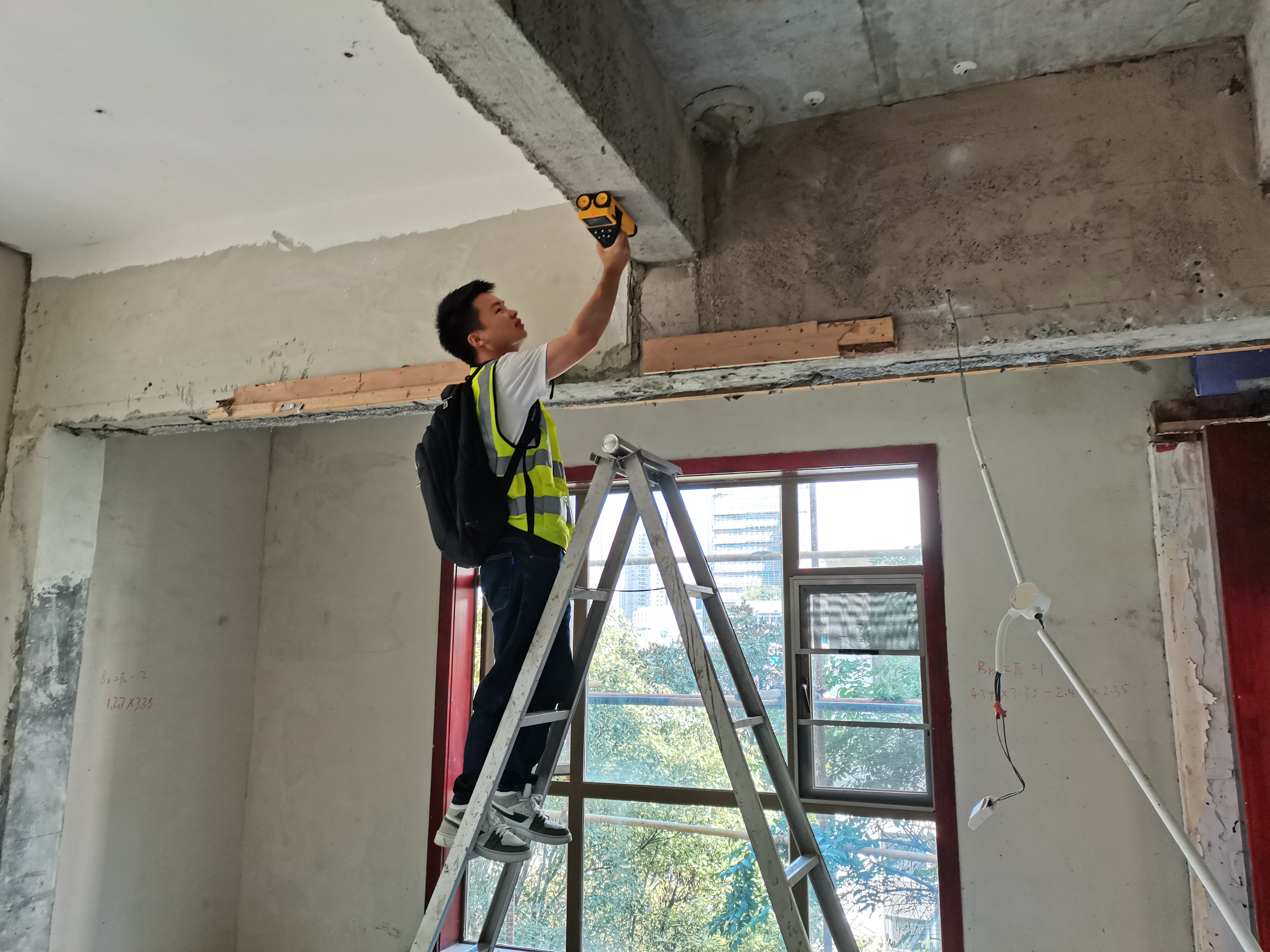
After each loading and unloading stage, the test should be continuously monitored for 10 to 15 minutes; under higher test load conditions, for 30 minutes. During the delay period, observe the reaction of the test components. Record all readings upon completion. Deflection of the components can be observed using an internal diameter gauge, angular displacement sensor, level gauge, etc. When using an equivalent circuit to simulate uniformly distributed loads, the average deflection error should be multiplied by the correction factor. For a three-point loading, the correction factor is 0.98. For other methods of concentrated loading, the correction factor should be calculated accurately. Stress detection of steel frame components can be conducted using a ground stress magnetometer or a resistive strain gauge.