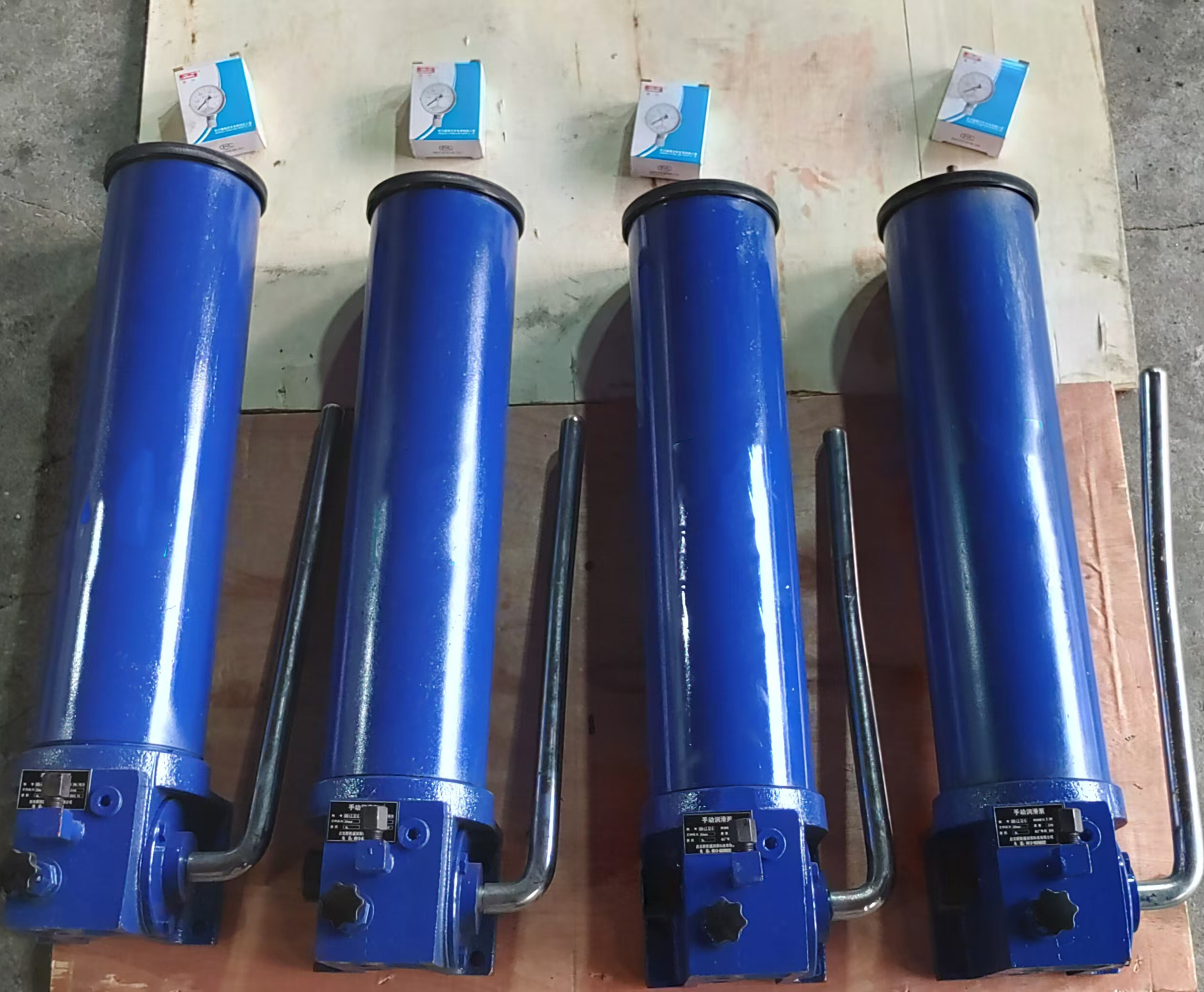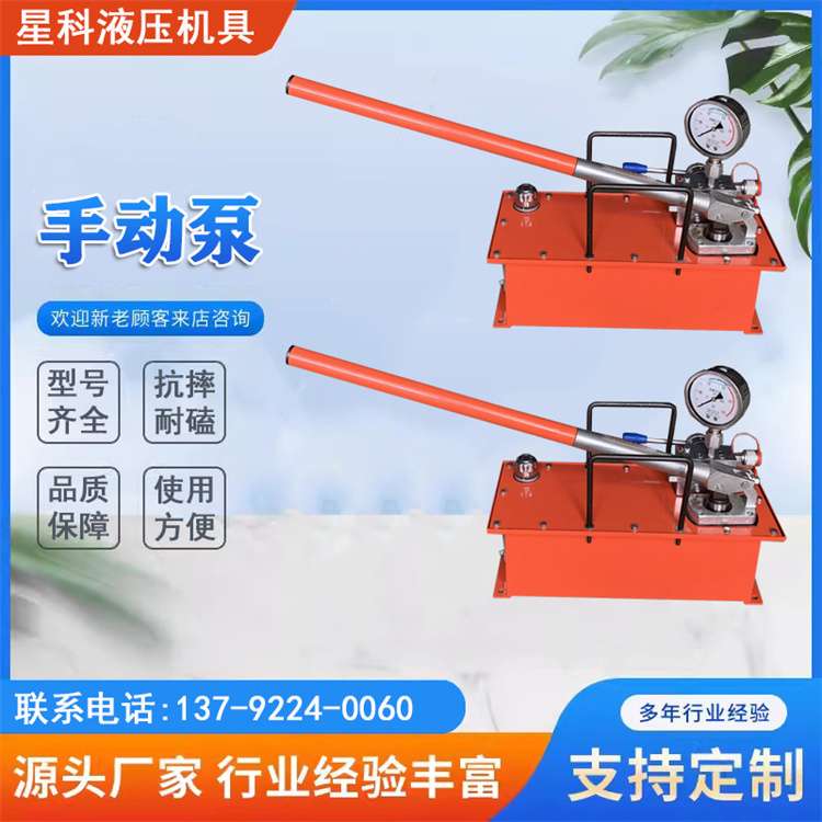


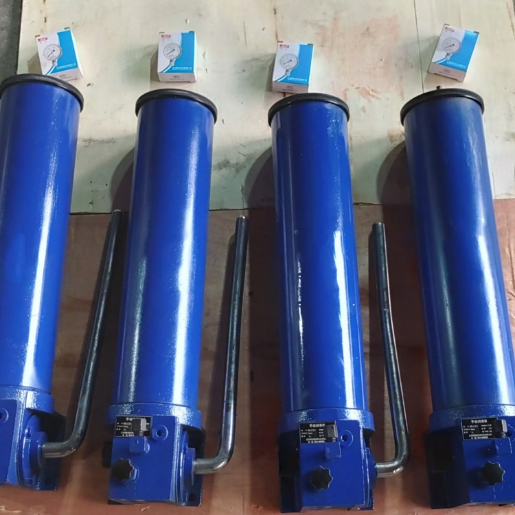


SRB-J/L Series Manual Lubrication Pumps (10MPa, 20MPa)
I. Overview
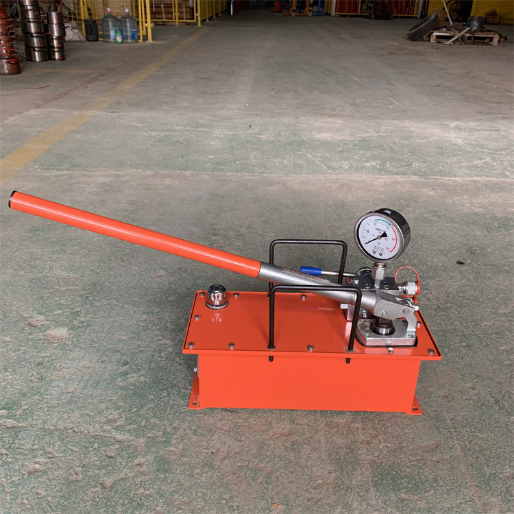
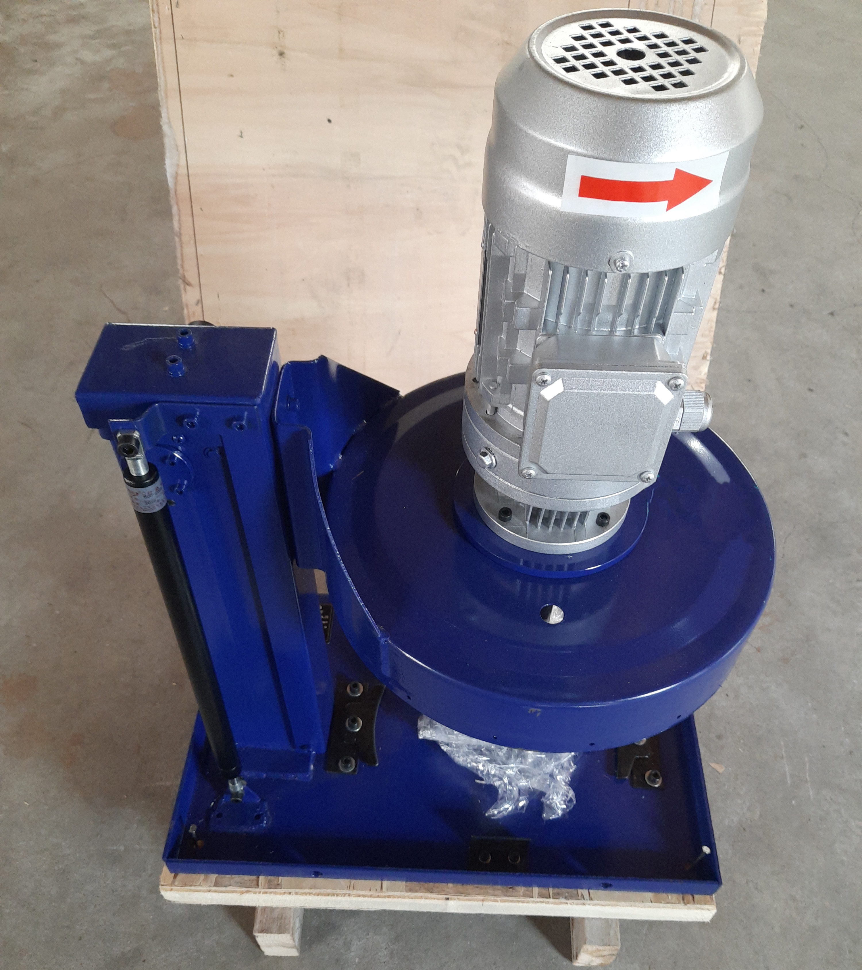
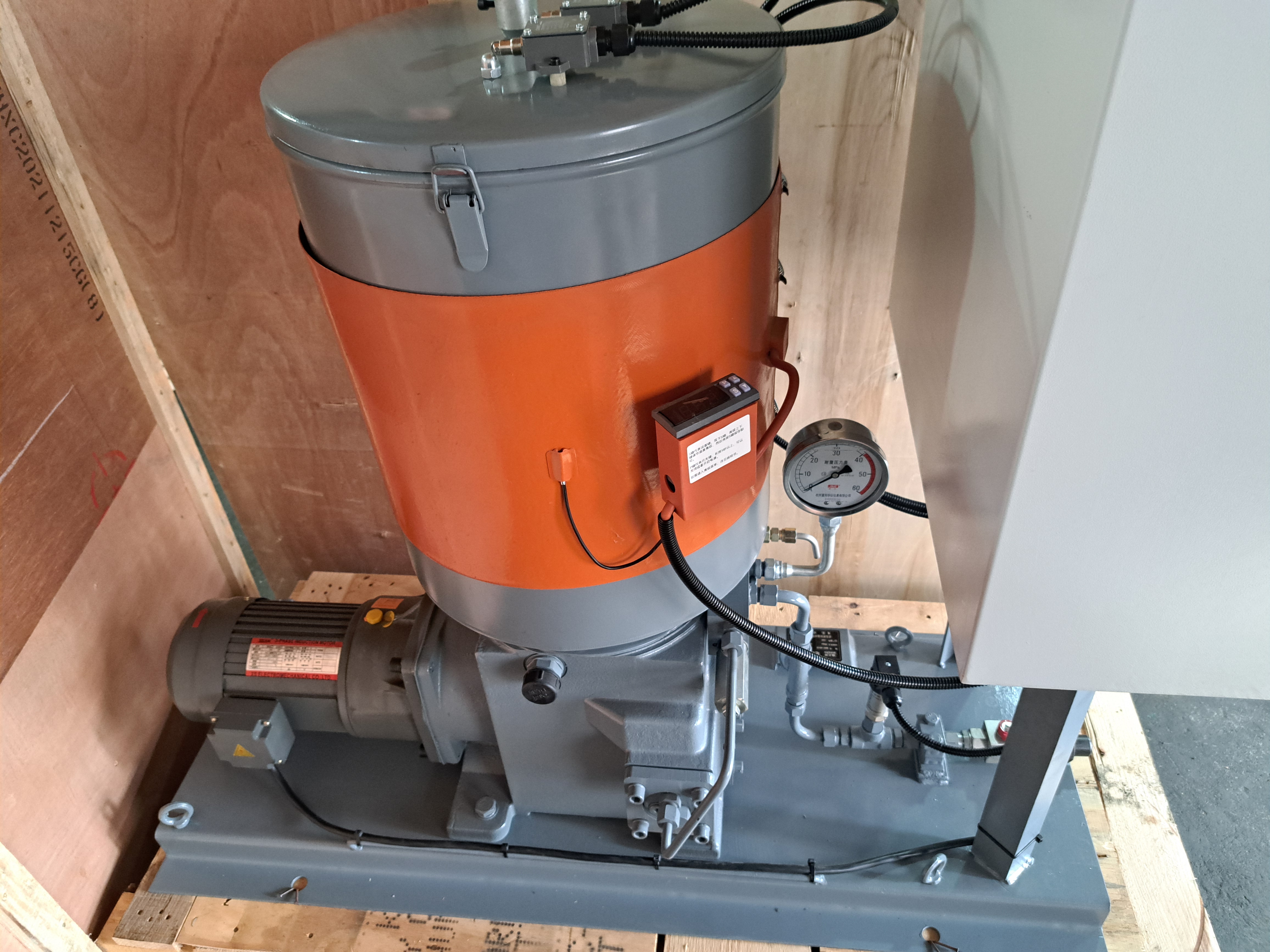
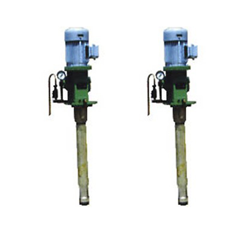
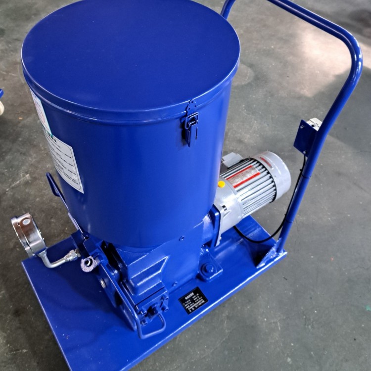
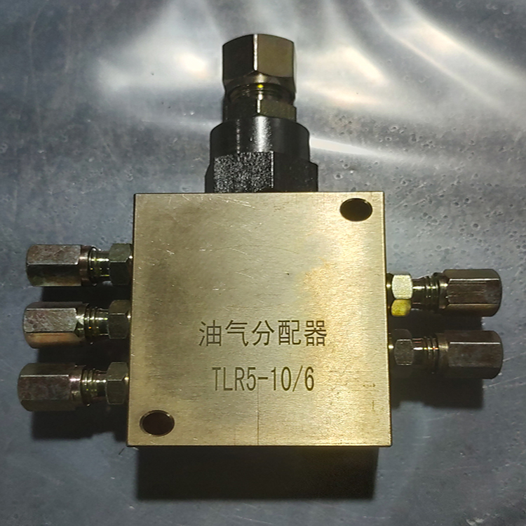
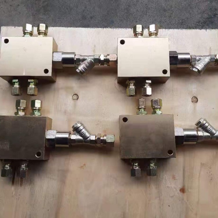
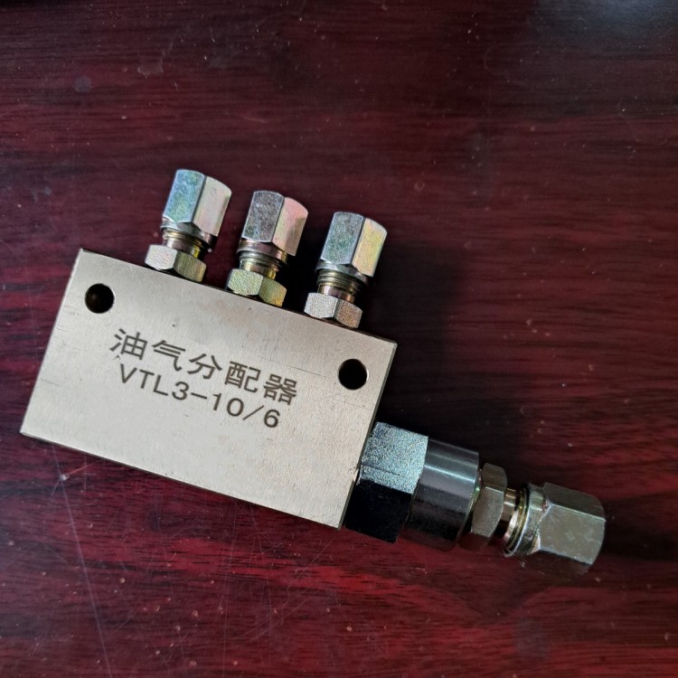
This unit is a compact lubrication pump that can be directly mounted on a machine's wall or frame. Operated manually by turning a handle, it expels lubricant. It can be paired with a two-line distributor to form a manual centralized lubrication system, delivering a precise amount of lubricant to various lubrication points on the machine. It is suitable for single-unit small equipment with a lower frequency (typically oiling intervals of 8 hours or more), piping (DN 15) length not exceeding 50 meters, and no more than 80 lubrication points, serving as a centralized lubrication device for supplying lubricant.
II. Technical Specifications
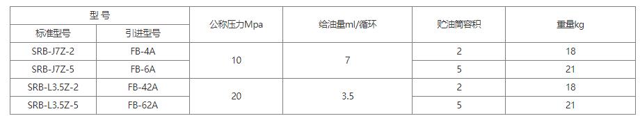
Lubricants with a penetration of 310-385 (25°C, 150g) 1/10mm (NLGI 0#-1#) and oils with a viscosity grade greater than N68 are used, suitable for ambient temperatures of -10°C to 40°C.
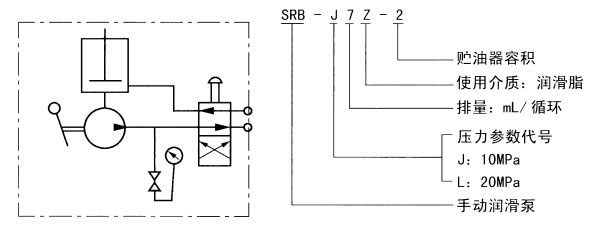
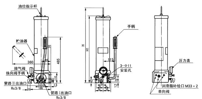
3. Schematic Diagram
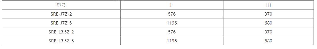
Four: Dimensions
V. Action Description
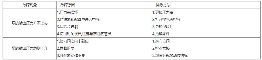
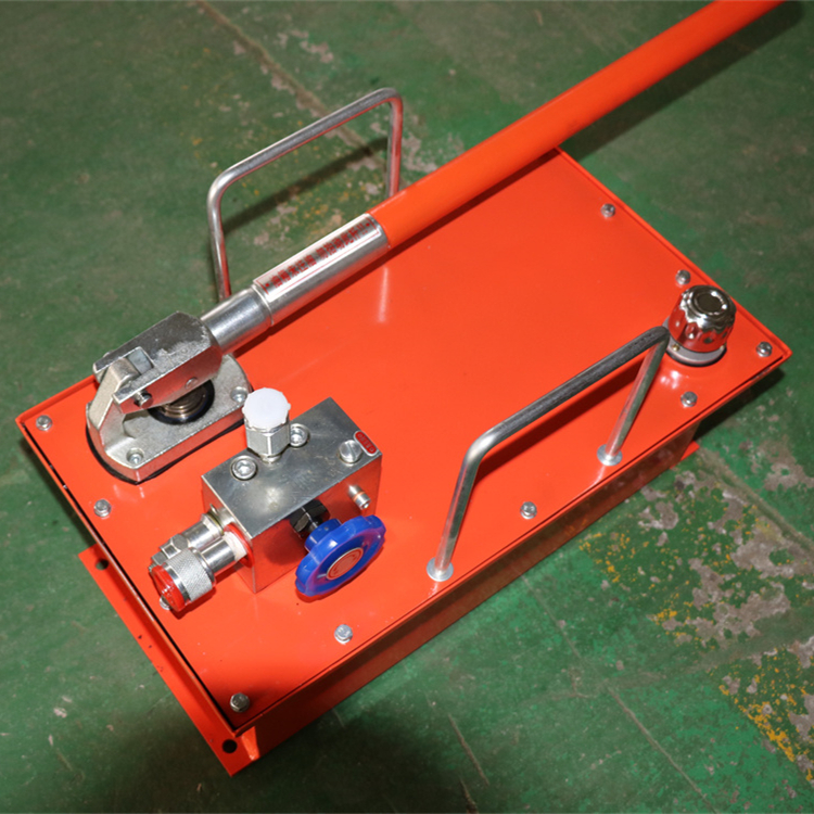
The manual lubrication pump supplies grease by manually operating the handle, which drives the toothed plunger to reciprocate through a small gear. When the plunger reaches the right end limit position, the right end chamber stops pressurizing oil, and the left end chamber finishes absorbing oil. As the handle is moved, the plunger moves to the left, first closing the left chamber's intake, squeezing grease to overcome the one-way valve and flow through the directional valve into the main supply line II for discharge; at this point, the volume of the right plunger chamber increases, creating a vacuum, which gradually intensifies. When the plunger moves to the left end limit position, the right chamber's intake opens, and under atmospheric pressure, grease is drawn in. The reverse action occurs, with grease overcoming the one-way valve and flowing through the directional valve into the main supply line JJ for discharge. The direction change during the supply process is achieved through the directional valve. When the directional valve handle is pushed in, grease is discharged from main line II; when the handle is pulled out, grease is discharged from main line I.

Section 6: Operating Procedures
Push the directional valve handle to the full position, and supply oil through the main supply line II.
2. The handle moves forward and backward, the pressure gauge pointer fluctuates, proving that the series distributor is supplying oil.
3. The pressure gauge on the pump indicates a stable increase in pressure value, proving that all the system distributors have completed their operation.
4. Pull the directional valve handle to its full extension position, initiate oil supply through the main oil supply line I, and proceed with the operations as per steps 2 and 3.
5. Release pipeline pressure, switch to main oil supply II, prepare for the next cycle, and turn the handle to the vertical position.
Section 7: Instructions for Use
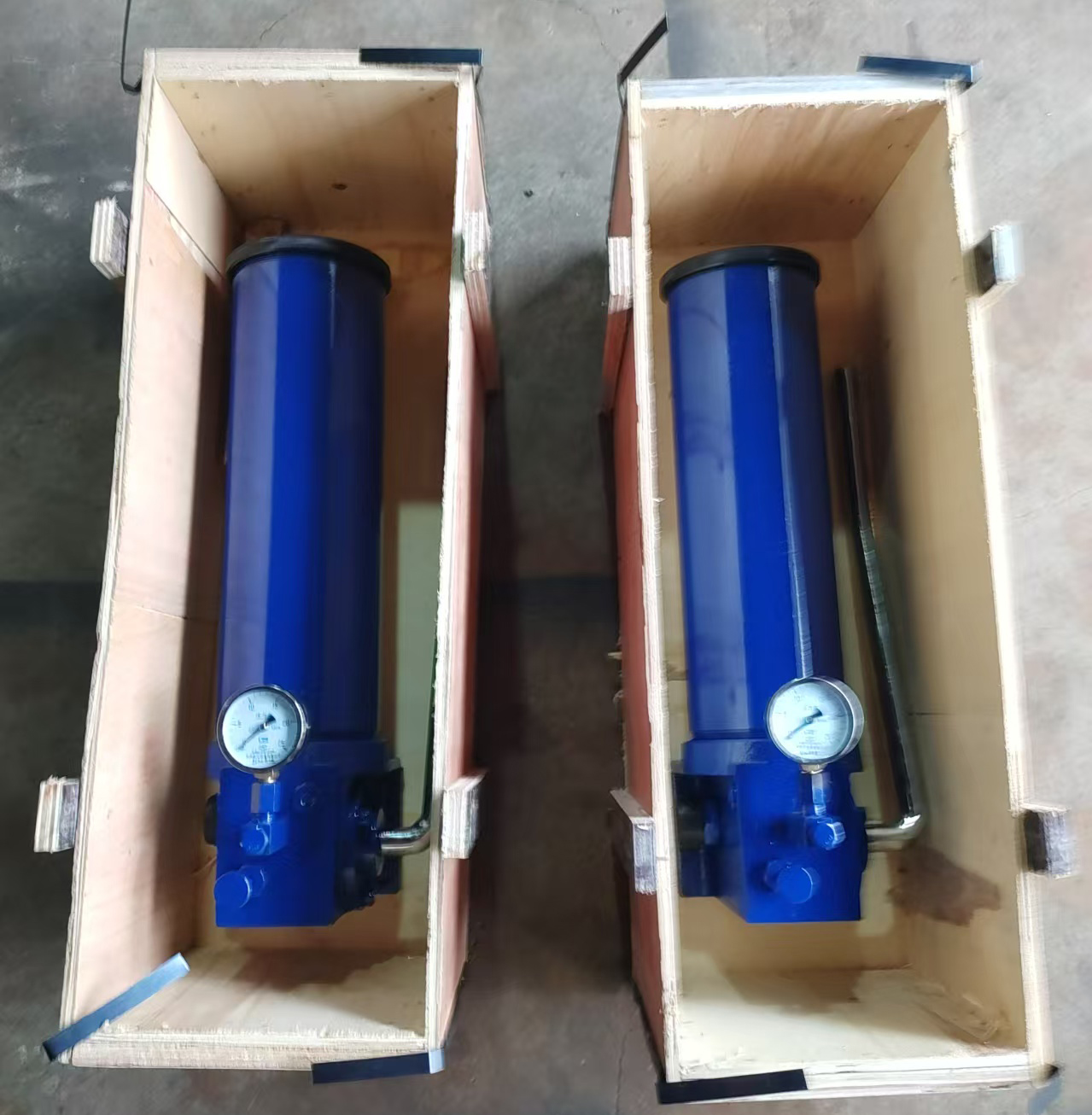
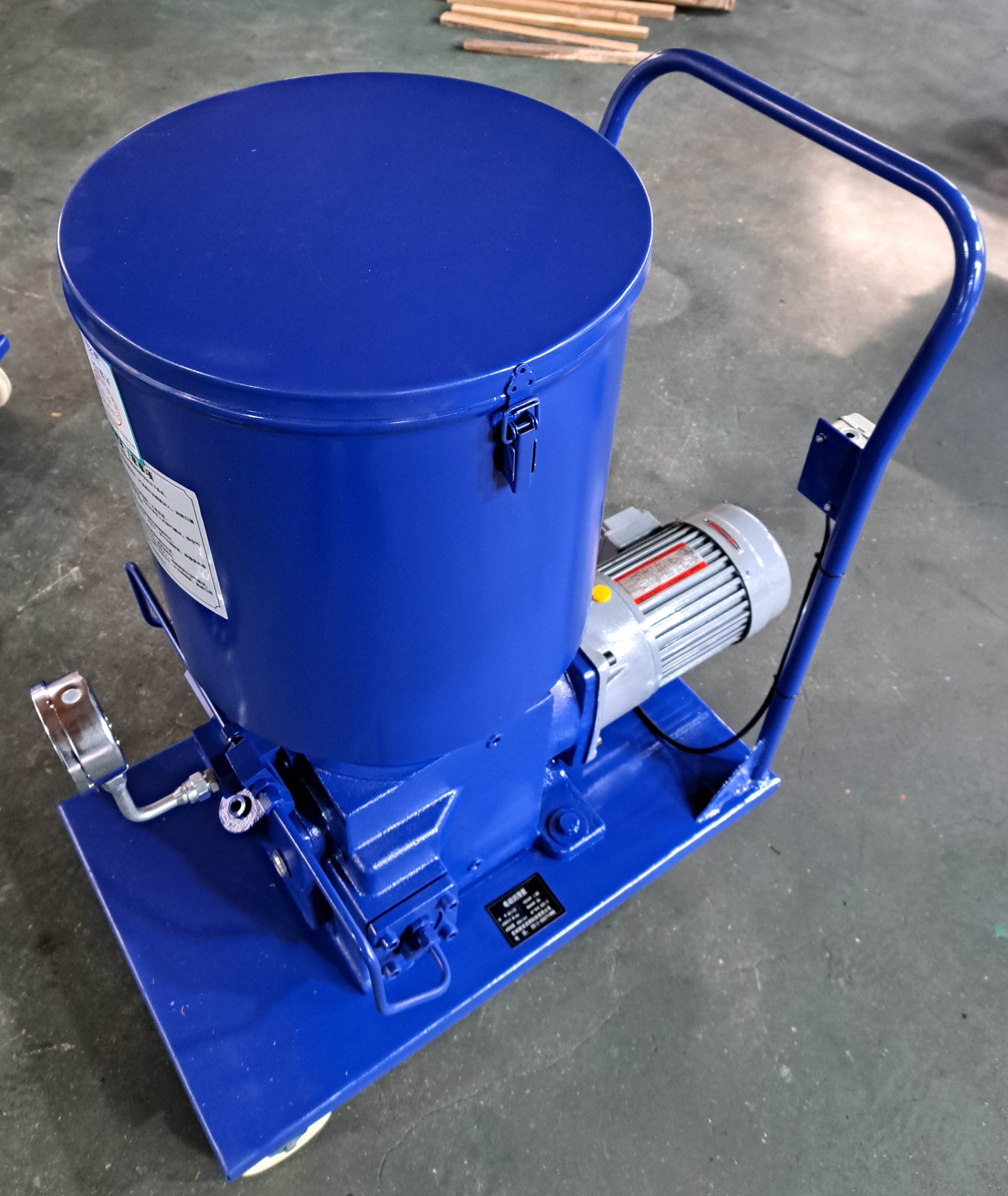
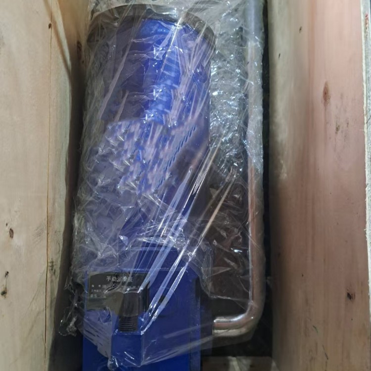
1. The manual lubrication pump should be installed vertically, with enough space for the indicator rod to rise and for replenishment operations around the pump. When installing in outdoor or harsh environments, the pump should be placed inside a protective cover.
2. Do not operate the handle if there is no lubricant in the oil storage tank; the oil level at the bottom should be replenished with lubricant promptly.
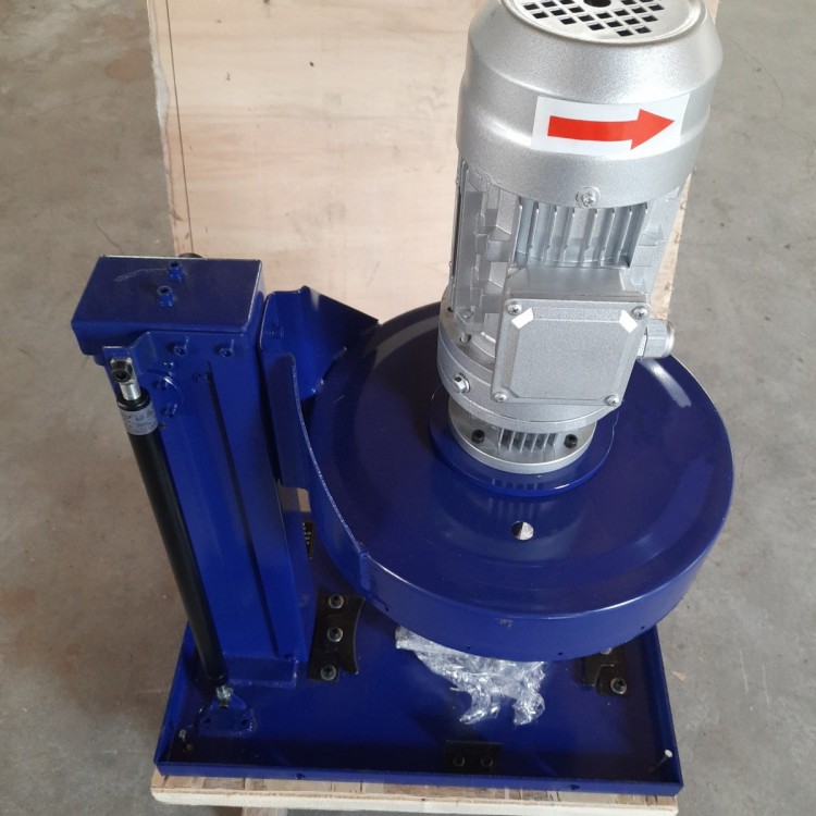
3. Fill the oil reservoir with grease, using only a dedicated manual or electric grease pump from the filling port.
4. The pump's operating pressure must not exceed the pump's nominal pressure.
5. The filter screen of the pump oil filling port should be regularly inspected and cleaned.