


DRB-P Series Electric Lube Pumps and Units (40MPa)
I. Overview
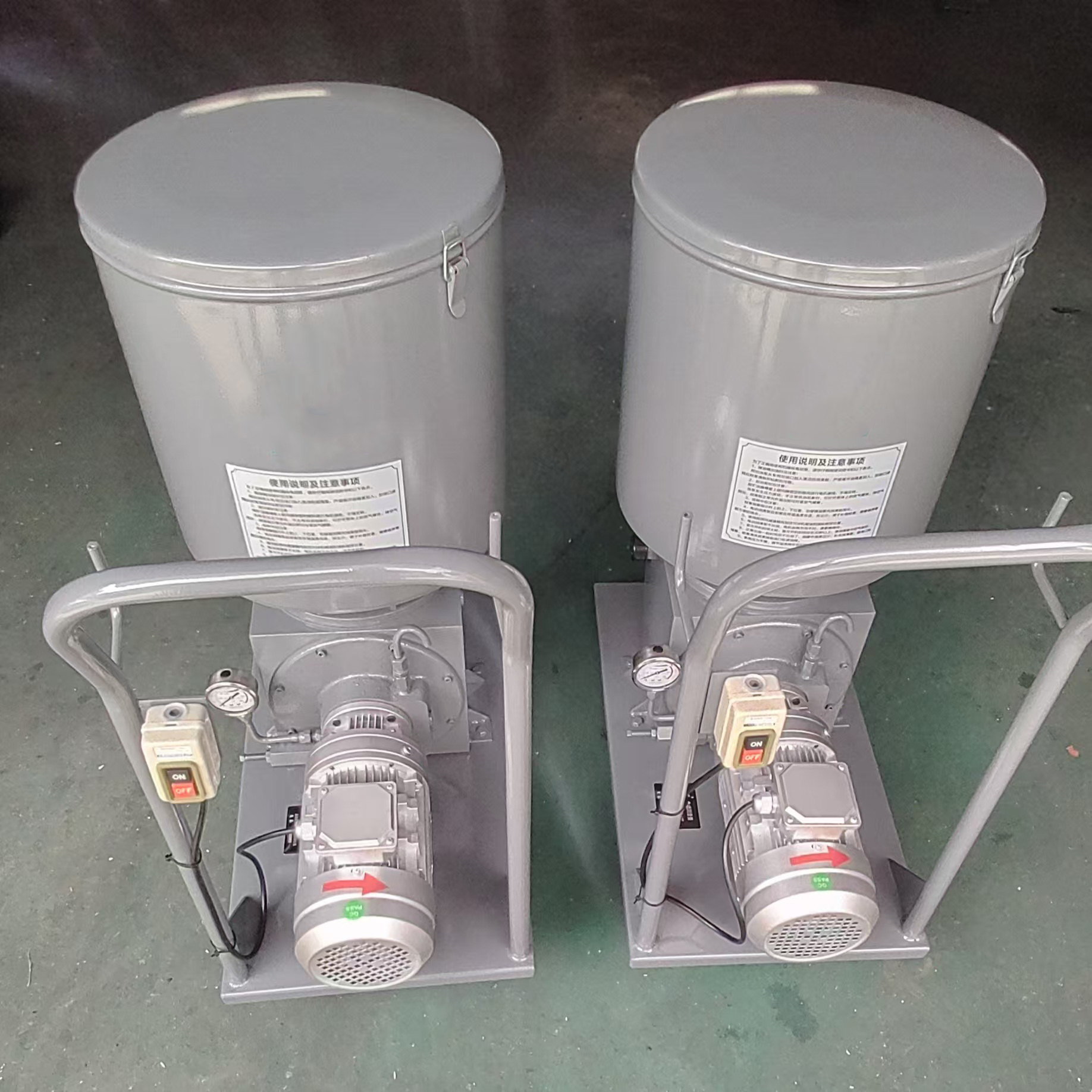
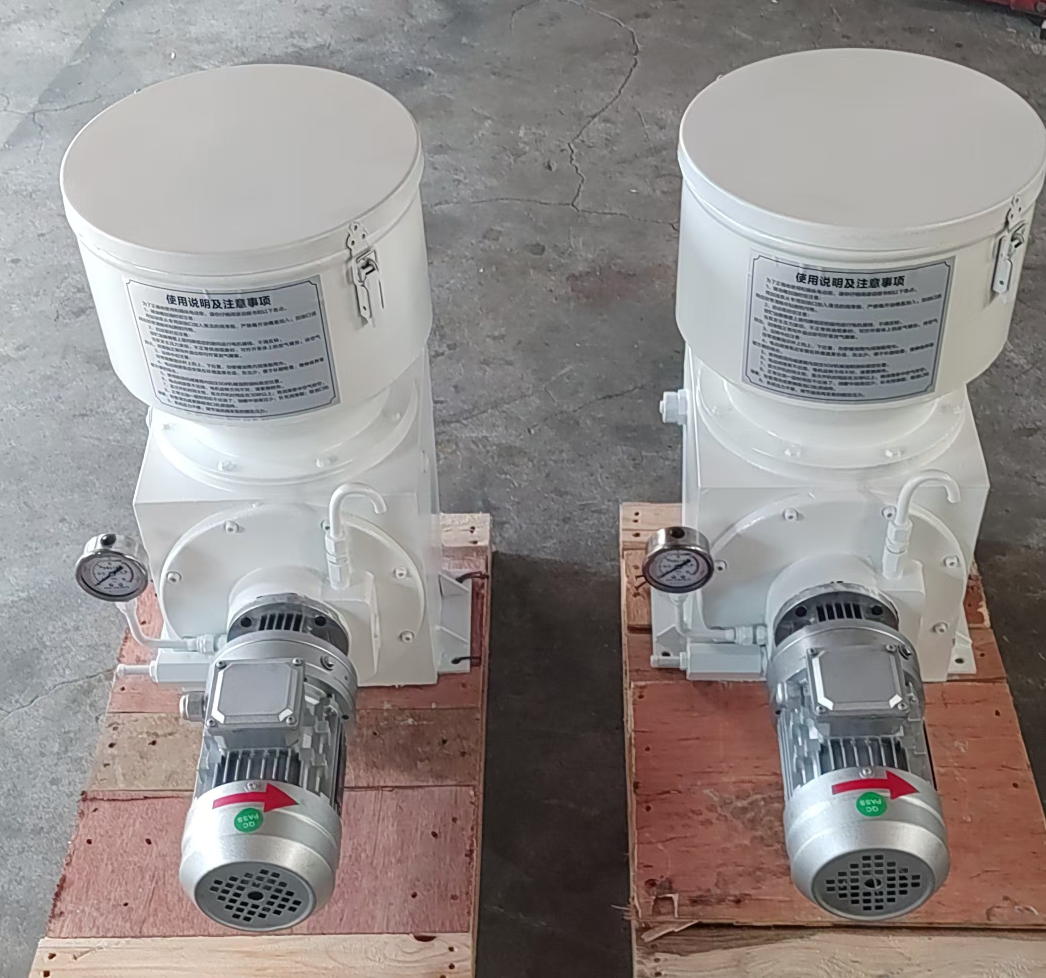
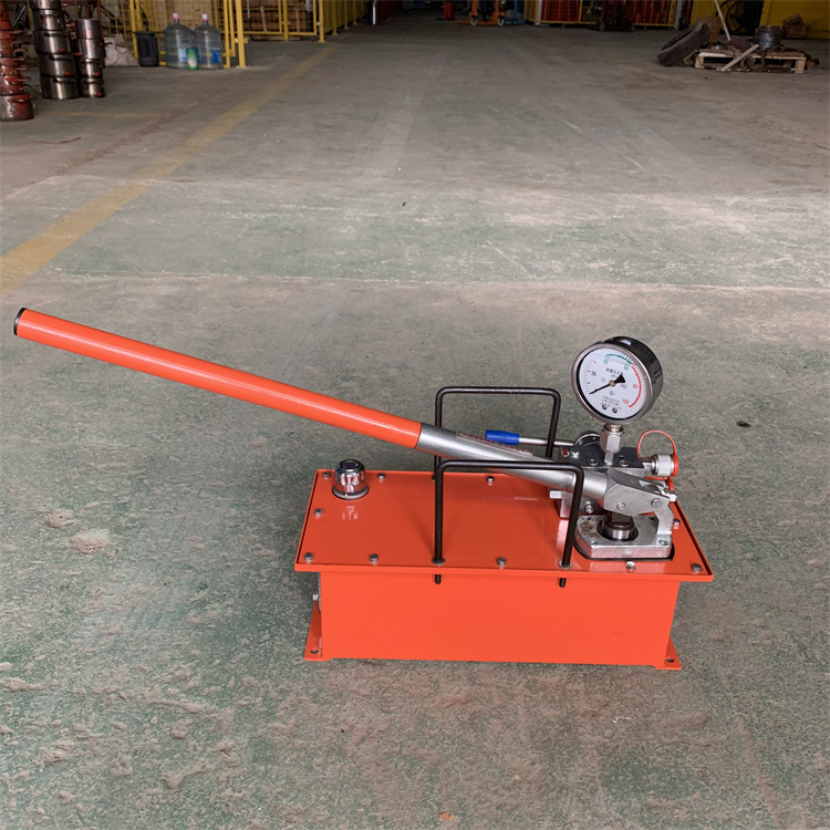
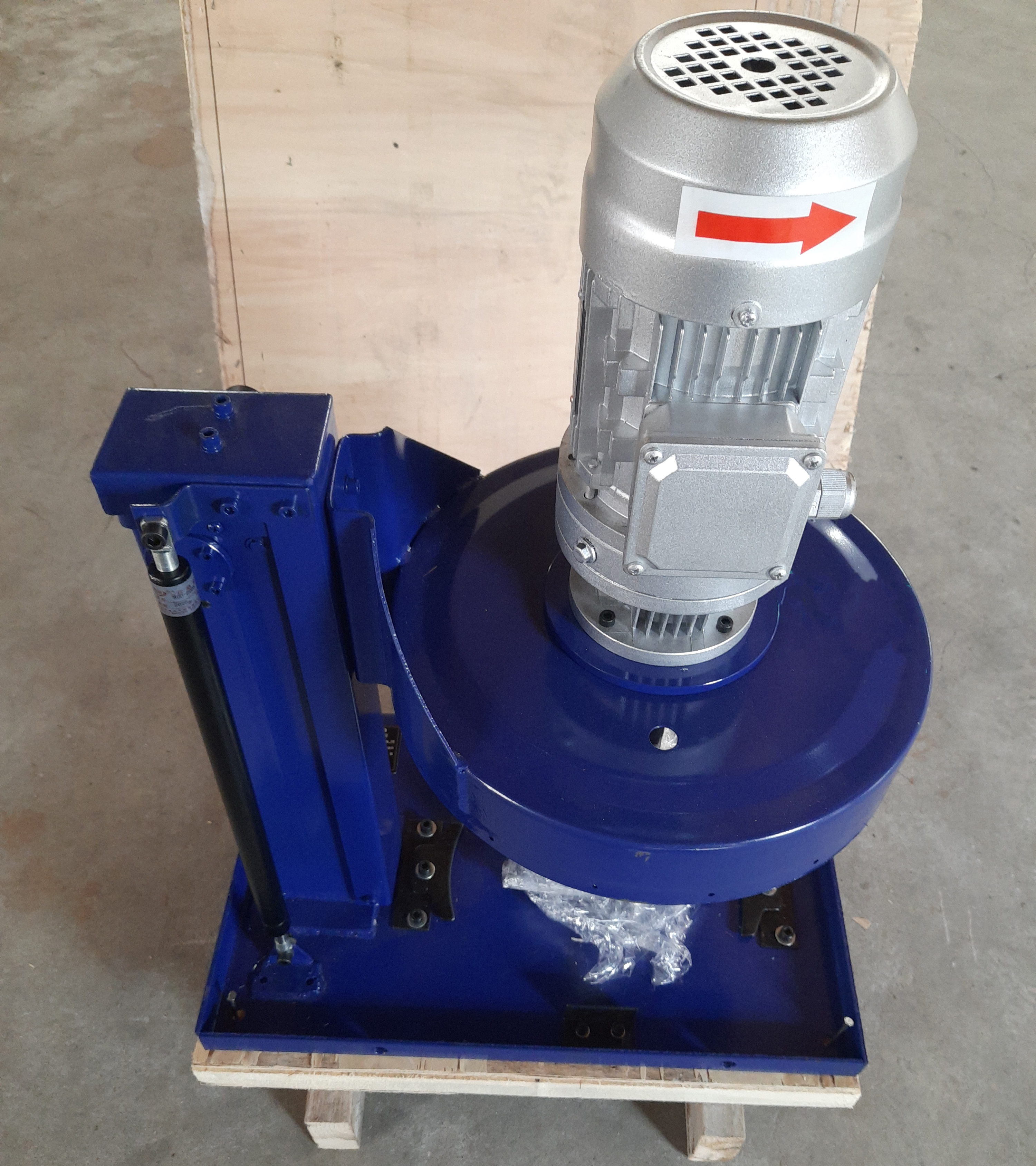
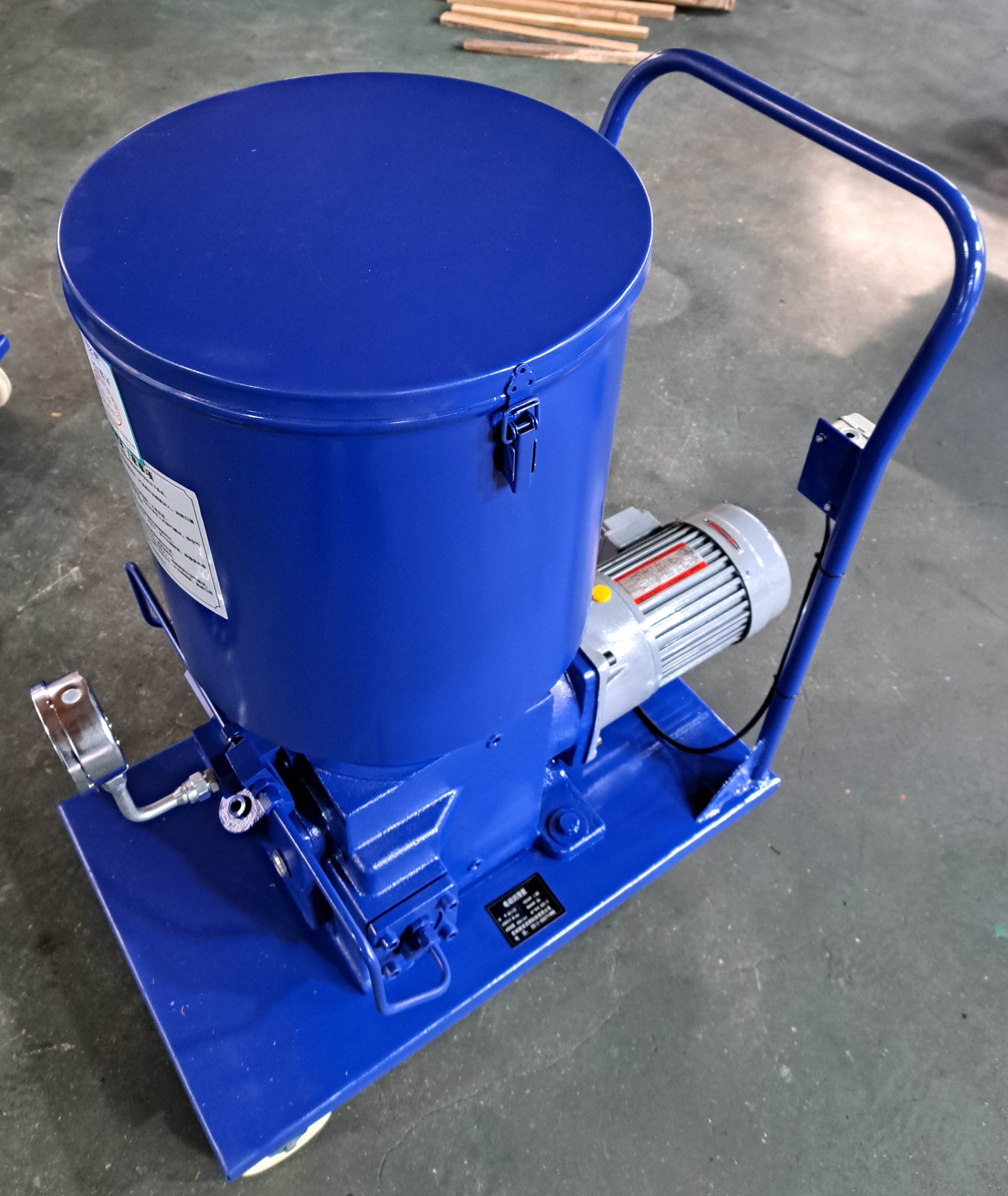
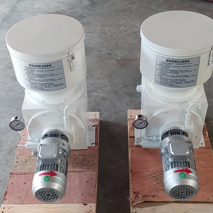
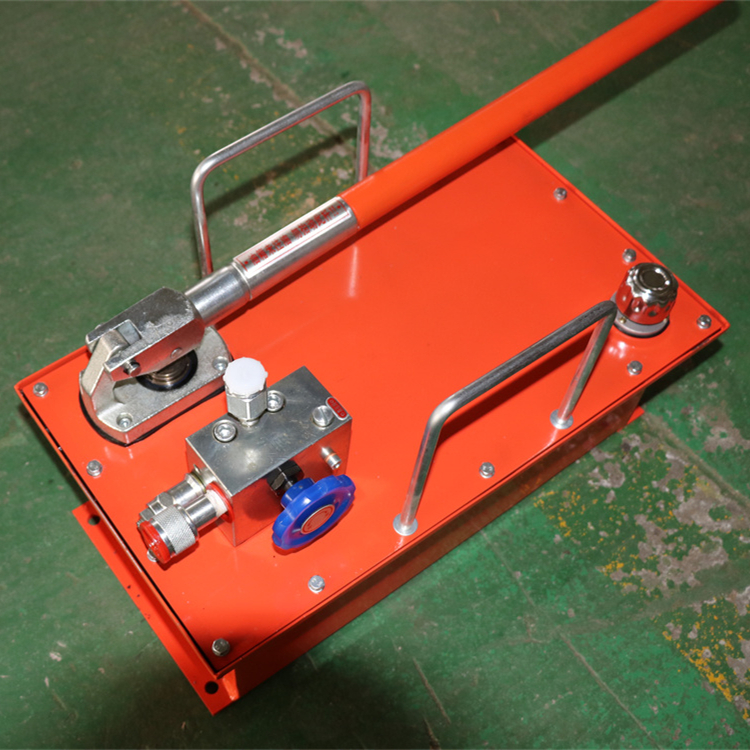
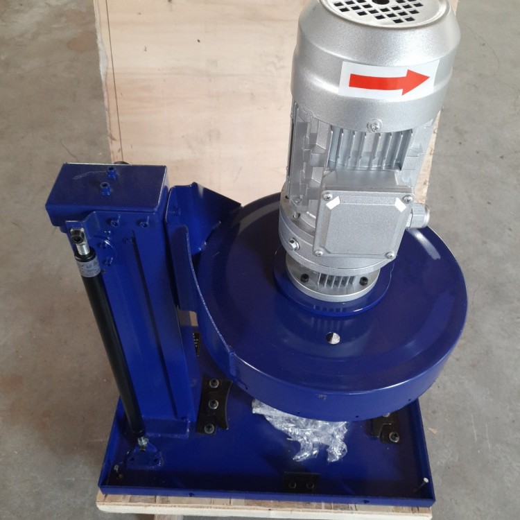
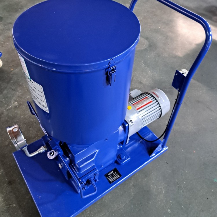
The DRB-P series electric lubrication pumps are suitable for single or double-line centralized lubrication systems with high lubrication frequency, long piping lengths, and dense lubrication points, serving as a lubricant supply device. They can also be equipped with mobile trolleys, hoses, oil guns, and cables to form a portable electric lubrication pump unit, ideal for single-machine equipment with low lubrication frequency, fewer lubrication points, large oil supply, and where centralized lubrication is not feasible.
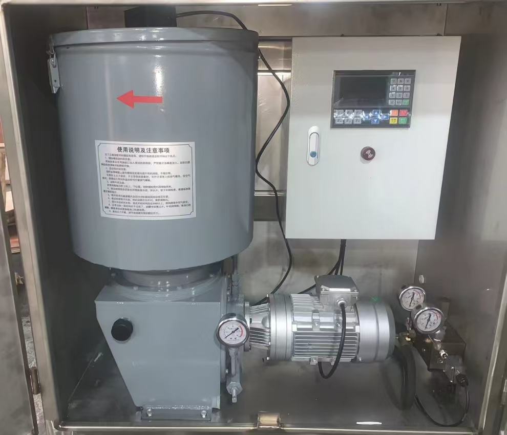
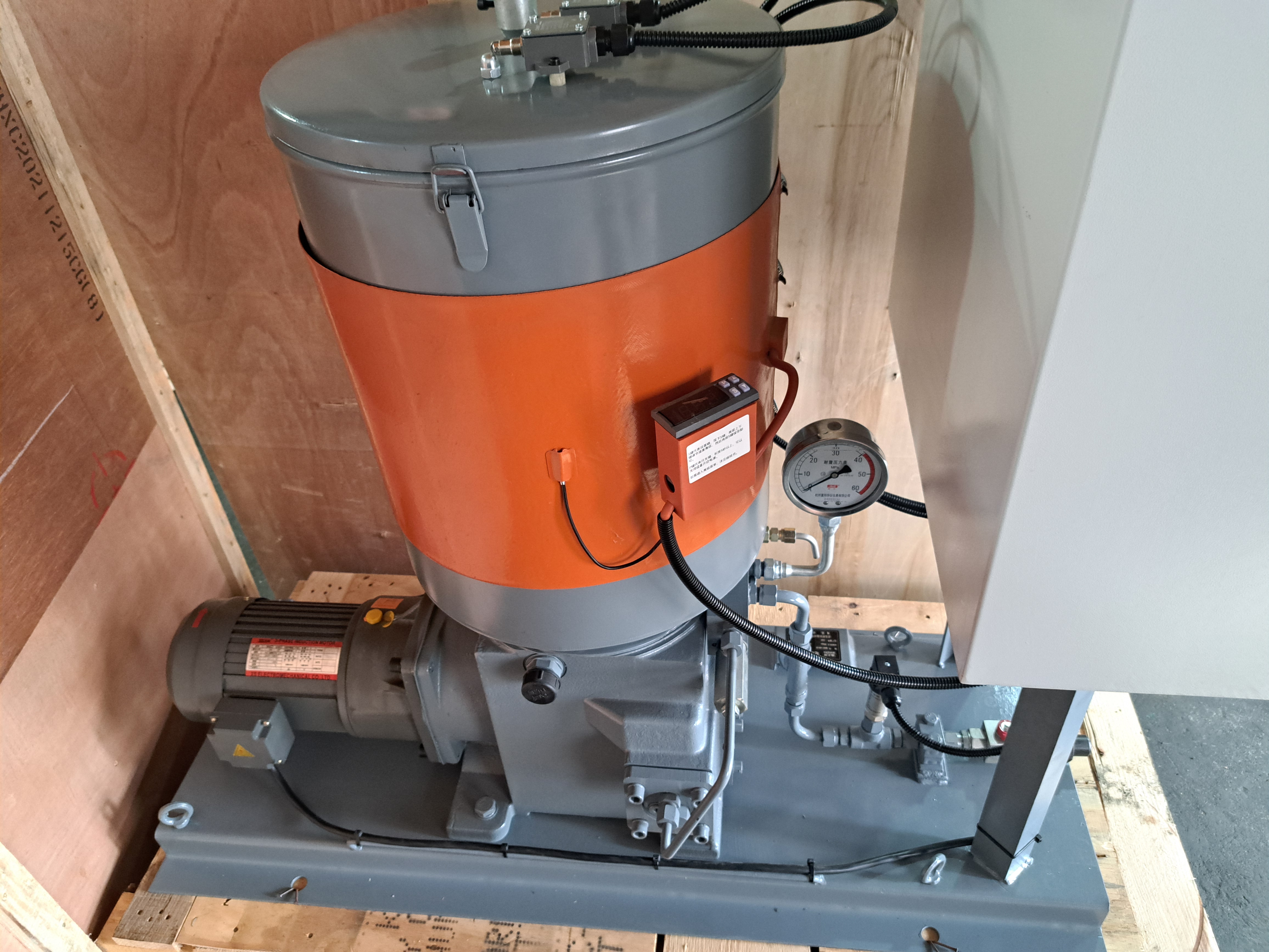
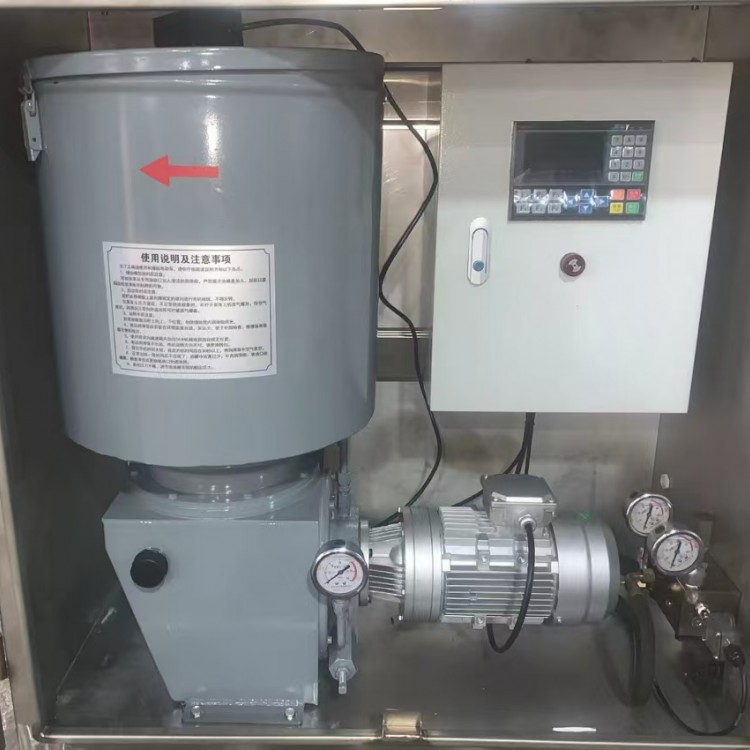
This series of lubrication pumps is an electric high-pressure plunger type. The working pressure can be adjusted freely within the nominal pressure range and features dual overload protection. The oil storage tank is equipped with an automatic oil level alarm. If the lubrication pump is fitted with an electrical control box, it can achieve full automatic control of a dual-line centralized lubrication system and monitor the system.
II. Technical Specifications

Use grease with a penetration not less than 220 (25°C, 150g) 1/10mm (NLGI 0#-3#) and oil with a viscosity grade greater than N68.
Section 3: Model Description
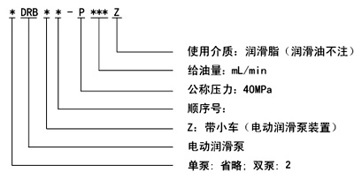
Section 4: Model Description
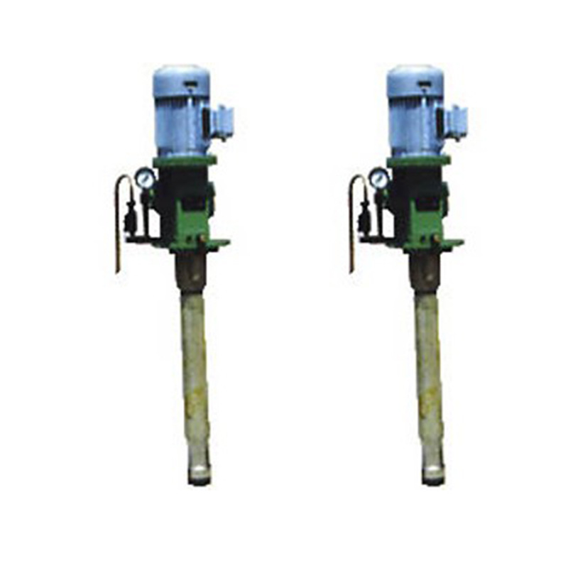
Section 5: Dimensions
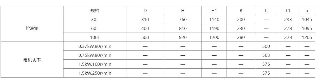
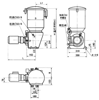
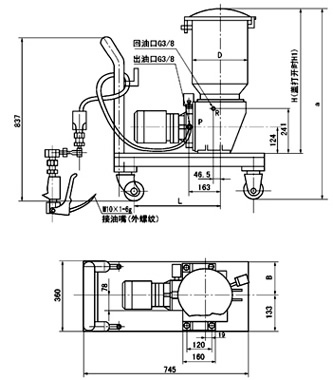
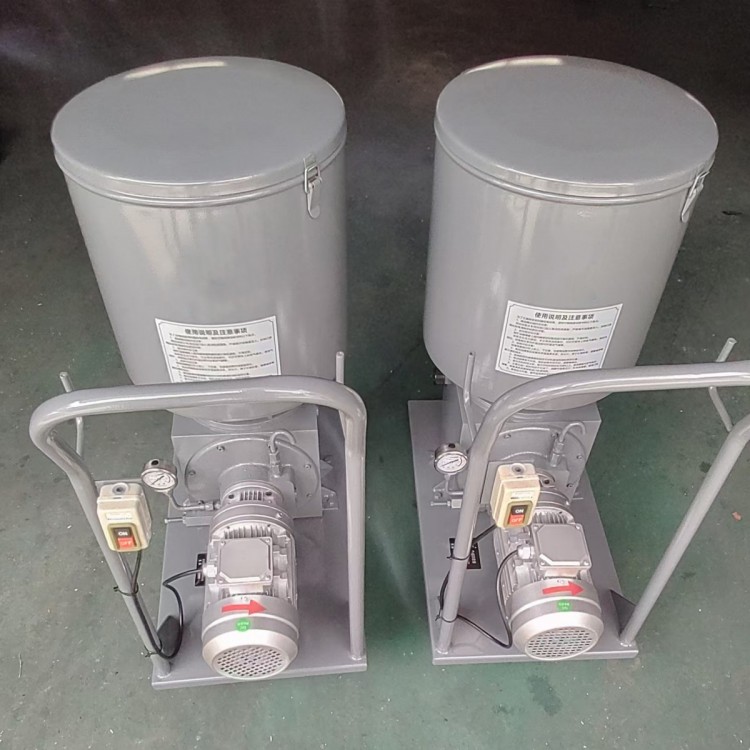
(1) External Dimensions of the Lube Pump (2) Lube Unit with Small Cart - Dimensions
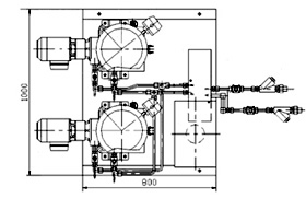
(3) Double-pump with electric reversing valve lubrication unit exterior dimensions
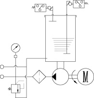
Six: Working Principle
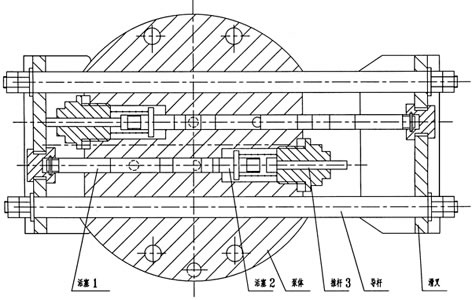
The decelerating motor is mounted on the connecting flange of the pump assembly, driving the slider to perform a straight reciprocating motion through the eccentric shaft, and rotating the spiral oil-pressing plate and scraper plate clockwise (this mechanism is not present when using lubricating oil), uniformly pressing the softened grease around the pump assembly's oil intake.
The pump housing contains two sets of pistons, each set consisting of one working piston and two control pistons. When the working piston of one set completes the suction process, the working piston of the other set pushes grease towards the outlet. As shown in the figure below, when the slider moves to the left, the upper set of pistons completes the suction, while the lower set completes the pressure. A new working cycle begins. At this point, pistons 1 and 2 of the lower set move to the left; piston 2, under the force of the spring, reaches its limit position to close the outlet. Meanwhile, piston 1 continues to move to the left, forming a vacuum between pistons 2 and 1, which increases continuously as piston 1 moves left. When the slider reaches its limit position, piston 1 opens the suction port, and grease is drawn in. If the spring force is insufficient to push piston 2 to its limit position, rod 3 will be forced to push piston 2 to its limit position by the slider's movement. At the same time, pistons 1, 2, and 3 of the upper set move to the left. Piston 1 closes the suction port first, and the grease drawn in moves to the left under the push of piston 1. When piston 2 opens the outlet, the movement of piston 2 and rod 3 stops. Piston 1 continues to move left, pushing grease out of the outlet. Pistons 1 and 2 have also moved to their limit positions, completing half a cycle. This process repeats continuously, with the two sets of pistons alternately pushing grease out of the outlet. The grease is then filtered through a filter on the pump's connecting flange before being supplied to the system.
Usage Tips
The series of electric grease pumps should be installed in an environment that is suitable, low in dust, and easy to adjust, inspect, maintain, and clean as well as convenient for replenishing grease.
2. The series of electric grease pumps should be positioned as centrally as possible within the system to minimize piping length and maintain the lowest pressure drop, enabling the pump to generate enough pressure to overcome the back pressure at the lubrication points.
3. The set pressure for the pressure regulating valve of the pump can be adjusted within the range of 0 to 40 MPa, and it is not allowed to exceed the nominal pressure of the pump (40 MPa) during use.
4. Regularly clean the filter screen at the pump outlet filter to prevent clogging.
5. In the event of a fault causing the pressure to reach approximately 50MPa in the series, the safety plate will burst. Investigate the cause and eliminate it before inserting a new safety plate.
6. Refilling the lubricant into the reservoir must be done using the DJB-H1.6 electric re-lubricator pump, adding through the reservoir's re-lubrication port.
7. The thin-film capacity indicator in the oil storage tank is only suitable for grease. When using a lubricating oil medium, it must be replaced with a float ball capacity indicator.
8. The electric reducer must be topped up with an appropriate amount of 3# molybdenum disulfide grease through the exhaust plug hole within the first two months of use. Subsequent top-ups should be done every four months.
9. This series of electric lubrication pumps is designed for indoor installation. Protective measures must be taken when used outdoors or in harsh environments.
Order Instructions
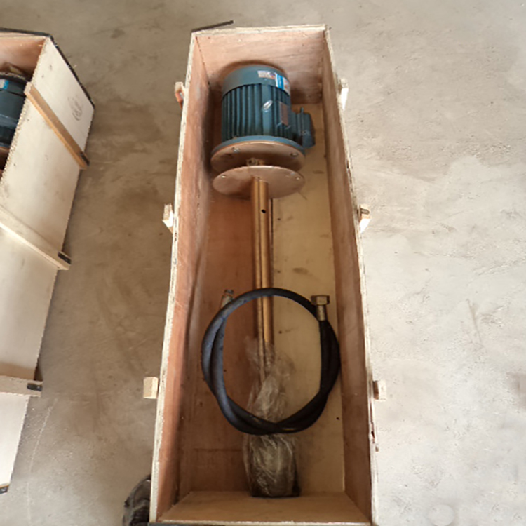
1. When ordering a portable electric lubrication pump unit, the contract must specify the length of the hose and cable. If not specified, the standard supply will be a cable of 10 meters and a hose of 3 meters.
2. This series of electric lubrication pumps is equipped with the following three types of standard electric control cabinets, which can be selected and ordered according to different control requirements.
2.1 Model GDK01 Unmonitored Electric Control Box
2.2 GDK02 Model with Monitoring Electric Control Box
2.3 GDK03 Model with Monitoring, Fully Automatic Control Electrical Cabinet
3. This series of electric lubrication pumps is designed for intermittent operation. If users require continuous operation for extended periods, please specify in the contract.
Supplied spare parts
1. 10 insurance plates (stored in the screw holes on the underside of the pump's oil outlet)
2. 2 sets of filter screens