


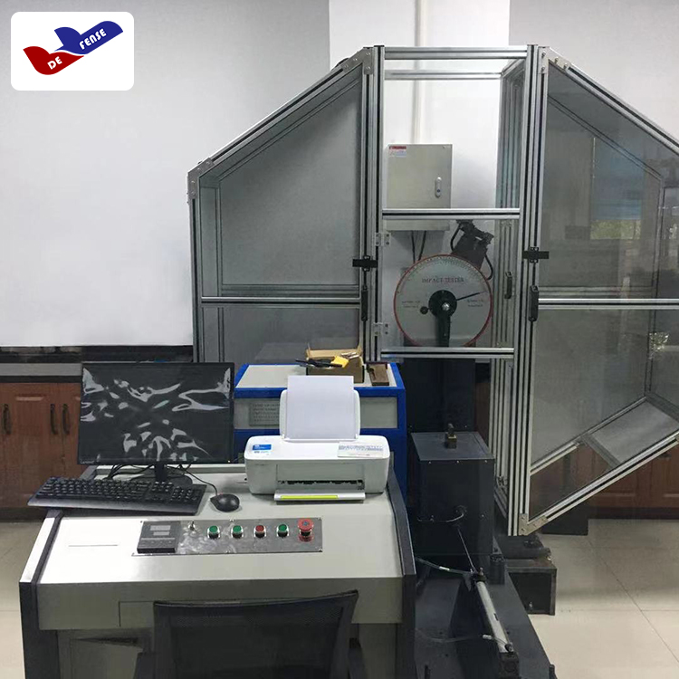


One,Overhang Beam Impact TesterFeatures:
This impact tester's main technical parameters comply with the requirements of ISO 180, GB/T 2611, JB/T 8761, and other standards. Its digital display is intuitive, the structure is simple, operation is convenient, and data accuracy is one of its key features.
Two、Overhang Beam Impact TesterTechnical Specifications
11. Operating Temperature (15-35)°C
12. Power Supply: AC 220±10% 50Hz
13. Impulse Speed: 3.5 m/s
14. Impulse Energy: 1J, 2.75J, 5.5J, 11J, 22J
15. Impact moment of force: Pd1 = 0.535 N·m
Pd2.75=1.4737N·M
Pd5.5=2.9474N·M
Pd11=5.8949N·M
Pd22=11.7898N·M
16. Accuracy: Angle (0.01°) Energy (0.001J)
17. Swing pendulum pre-tilt angle: 150°±1°
18. Center Distance to Knockdown: 335mm
19. Impact blade edge radius: 0.8 ± 0.5mm
10. Blade edge to jaw distance: 22 ± 0.2mm
11. Sample Type and Size. The best sample is Type 1, Model X. (Unit: mm)
Type A notch 45°±1° Radius at notch bottom R0.25±0.05mm
Type A Gap: 45°±1°, Bottom Radius of Gap: R1±0.05mm
Sample Type | Length L | Width B | Thickness D | |||
Basic dimensions | Extreme Tolerance | Basic Dimensions | Ultimate deviation | Basic Dimensions | Tolerance Limit | |
1 | 80 | ±2 | 10 | ±0.2 | 4 | ±0.2 |
2 | 63.5 | ±2 | 12.7 | ±0.2 | 12.7 | ±0.2 |
3 | 63.5 | ±2 | 12.7 | ±0.2 | 6.4 | ±0.2 |
4 | 63.5 | ±2 | 12.7 | ±0.5 | 3.2 | ±0.2 |
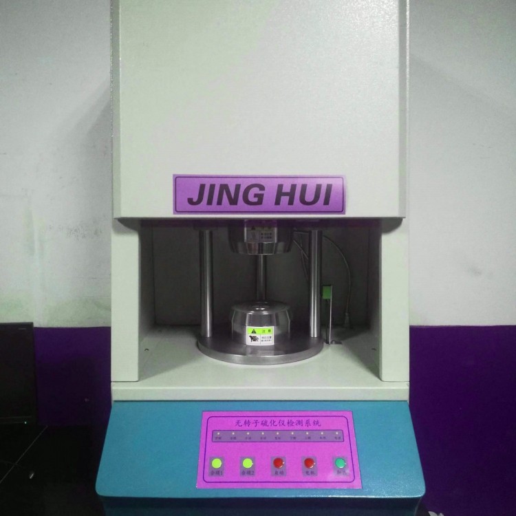
Three,Cantilever Beam Impact TesterStructure and Performance
This testing machine is composed of the fuselage, impact pendulum, specimen holder, measuring device, and control mechanism.
Body: Composed of a cross beam, an angle positioning mechanism, and a level.
2. Impulse pendulum: Composed of an upper connecting sleeve, pendulum rod, pendulum hammer, positioning block, and impulse blade, etc. The energy of the pendulum hammer is made up of 2 main pendulums and 4 sets of counterweights. The two main pendulums are a 1J pendulum and a large pendulum counterweight. There are 4 sets of counterweights, each with a 2.75J, 5.5J, 11J, and 22J weight (each counterweight is marked with steel impressions). Users can choose different counterweights according to their needs.
3. Sample Support: Consists of a clamp support and a clamp. Prior to testing, select the appropriate pendulum energy based on the sample requirements (test type).
4. Actuating Mechanism: Composed of a release mechanism and handle. This mechanism fixes the impact pendulum at 150° and automatically initiates the hammer impact.
5. Measurement Device: Consists of a digital acquisition system. Displays the energy consumed after the sample is impacted. The impact energy is calculated according to the following formula:
E=Pd (cosβ-cosα)
Equation: Pd - Impact Torque (constant)
α - Measured Impact Pendulum Pre-Angle (Constant)
β - Angle after impact
In this test, once the lift angle β is measured, the energy E value can be calculated. The digital display system of this testing machine is designed based on this principle, thus the data can be directly read out.