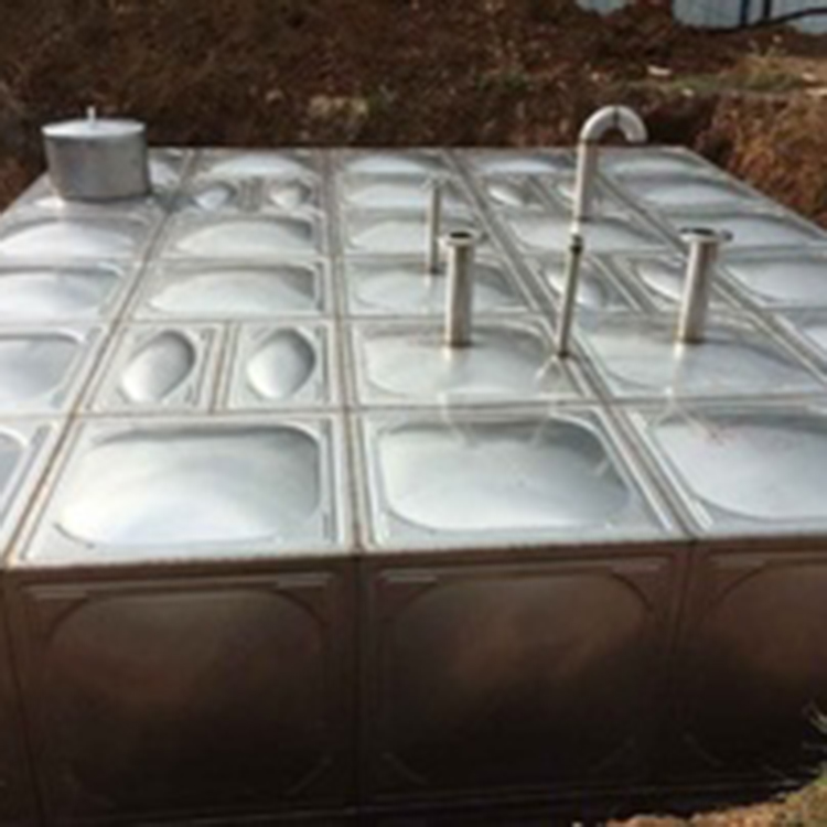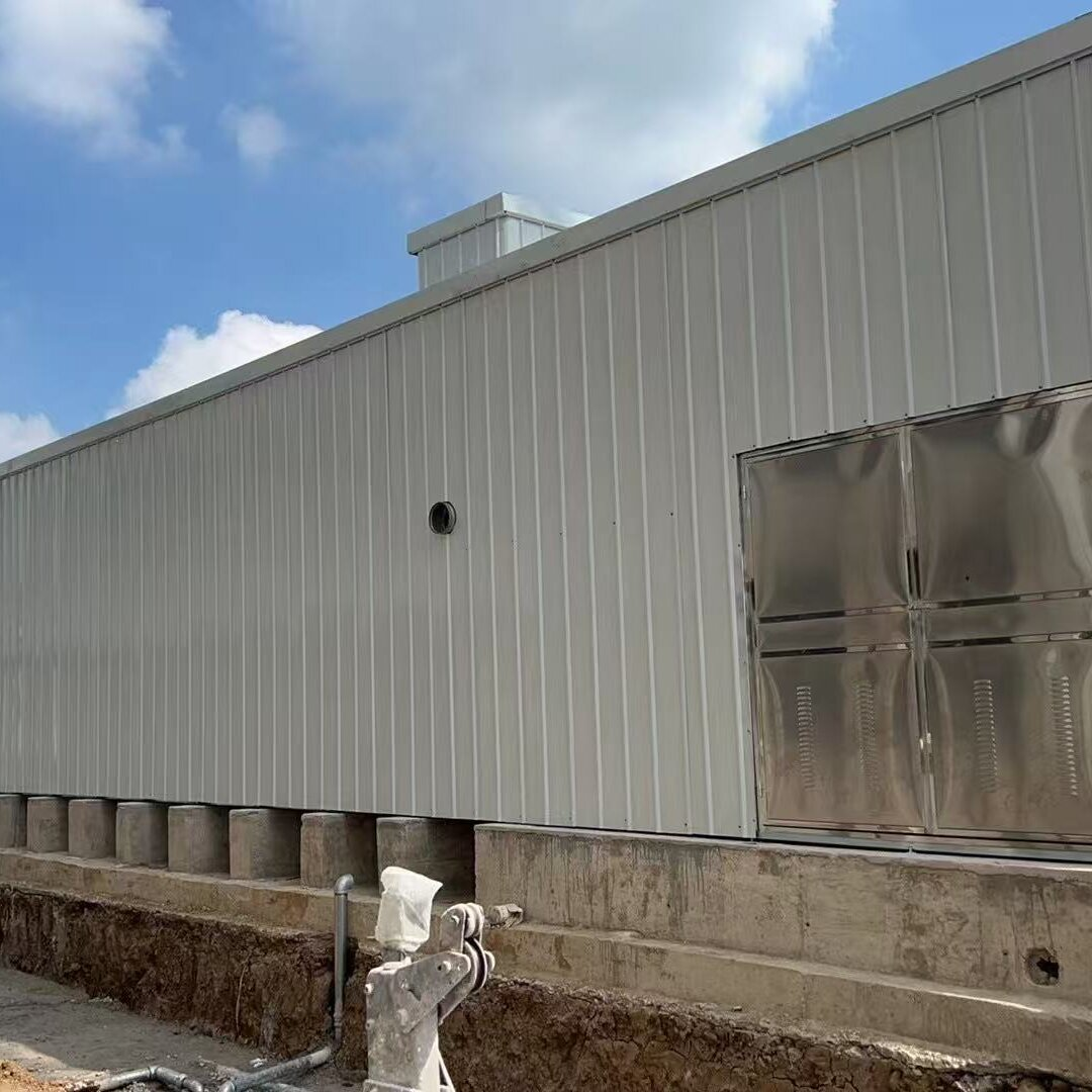


Yunnan Chuxiong Submerged Sump Pump Combination Fire Protection Equipment


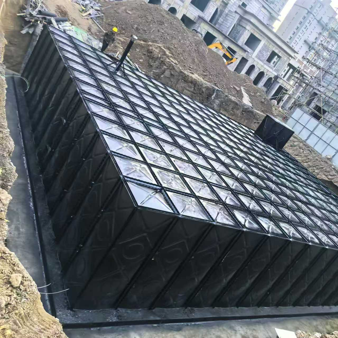
Newly Designed Subsurface Fire Protection Intelligent Integrated Pump Station
Fire Pump Station Design Description
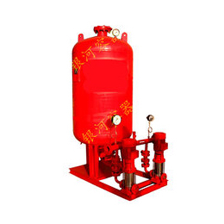
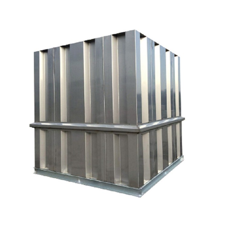
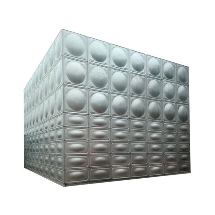
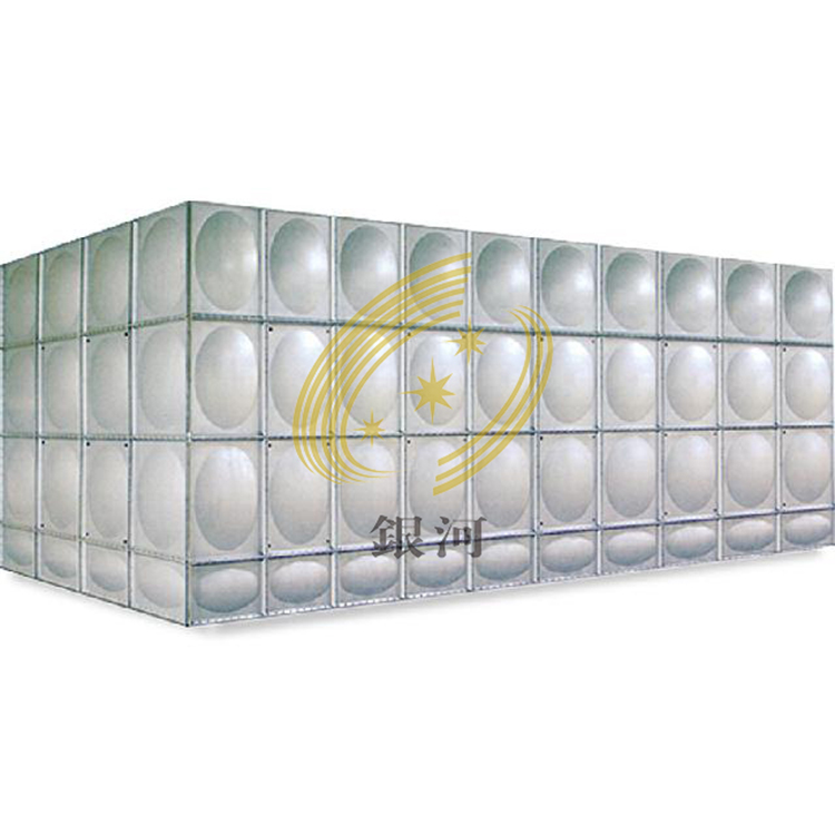
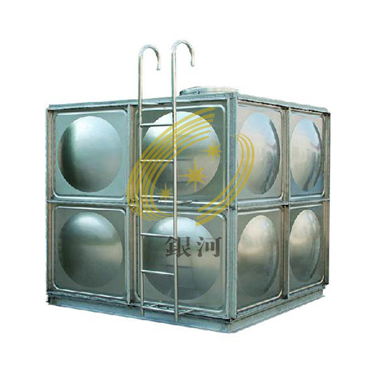
Pumping Station Composition: Composed mainly of fire reservoir, fire pump house, fire automatic constant pressure system, fire boost and pressure regulation system, gas top pressure equipment, and sewage system; Structural Form: All steel structure; Installation Form: Combined with bolt assembly and welding; Location: Underground; Material of Reservoir and Pump House: Hot-dipped galvanized steel, stainless steel, composite steel plate, or composite metal material; Internal Structure and Material of Reservoir: Full scaffold structure or portal steel frame structure; Hot-dipped galvanized steel pipe or composite plastic profile material; Internal Structure and Material of Pump House: Portal steel frame structure; Material: Hot-dipped galvanized I-beam or composite reinforced I-beam; Pump Station Load-bearing Capacity: 100-450KN/㎡; Service Life: ≥70 years; Buoyancy Resistance: Calculation in accordance with Article 5.4.3 of the Design Code for Foundation of Ground; (Optional) Pump Station Foundation: Raft foundation; Seepage and Leak Prevention: Use of三元乙丙 rubber sealing strips; Pump Station System: Fire hydrant pump set and control cabinet, sprinkler pump set and control cabinet, boost and pressure regulation pump set and control cabinet, gas top pressure system. Reservoir Breathing Tube: Designed at 1 per 10㎡ according to the reservoir flat size, manufactured in accordance with the requirements of 12S101-95, and in compliance with Article 4.3.10 of the Technical Specification for Fire Water Supply and Fire Hydrant System; Overflow Pipe and Drainage Facilities: Overflow pipe designed at twice the diameter of the inlet, and indirectly drained to the sump pit, manufactured in accordance with the requirements of 12S101-95; and in compliance with Article 4.3.9-3 of GB50974-2014; Drainage Pipe: Use of DN100 drainage pipe, and led to the sump pit; Reservoir Inlet: Dual water supply with gate valves, backflow preventers, filters, float valves, and set in the reservoir manhole; Inlet water adopts overhead water supply and is 150mm higher than the effective water level; Diameter calculated according to Articles 4.3.3 and 4.3.5 of GB50974-2014; Inlet water manufactured in accordance with the requirements of 12S101-94; Ventilation of Fire Pump House: Use of 24-hour passive ventilation, fully in compliance with Article 5.5.9 of GB50974-2014; Heating of Fire Pump House: Automatic constant temperature device is set when the pump house temperature is below 5℃; Fully in compliance with Article 5.5.9 of GB50974-2014; Drainage Facilities in Pump House: A sump pit is set in the fire pump house with an effective volume greater than 5 minutes' output of one sewage pump, in accordance with Article 4.7.8 of GB50015-2009; Flow rate of sewage pump calculated based on discharge flow, emptying volume 100m³/h, additional 2m-3m head loss calculation for pipeline system water head loss, normally one in use and one in reserve, and both used at alarm water level, in compliance with Articles 4.7.7 and 4.7.8 of GB50015-2009 and Articles 5.5.9 and 5.5.14 of GB27898; Water Hammer Prevention Device: Slow-closing check valves are set on the outlet pipes of each pump, and a 24L bag-type air pressure tank is set on the main outlet pipe when the fire pump head exceeds 24m, in compliance with Articles 8.3.3 and 5.5.11 of GB50974; In compliance with the enterprise filing standard Q/320925SZG 002—2015.