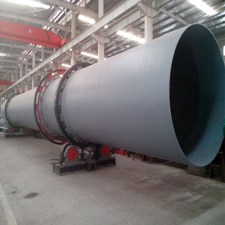


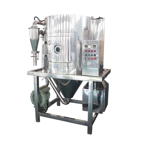


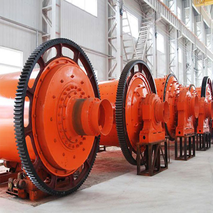
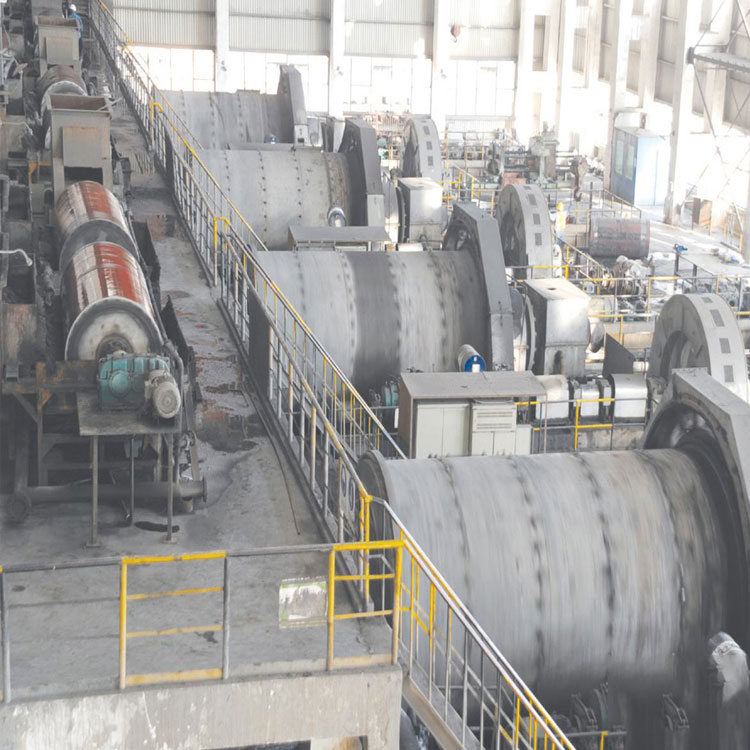
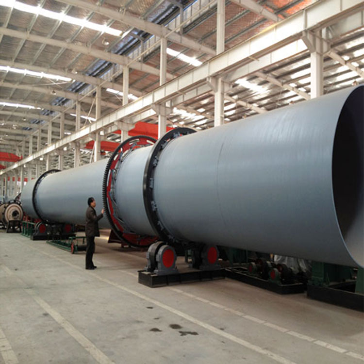
Introduction to Mining Drying Machine
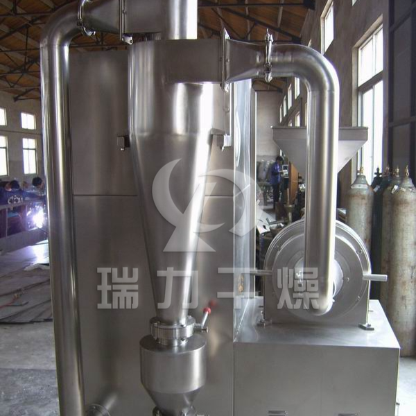
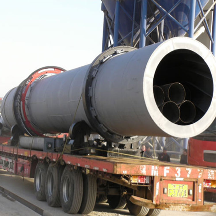
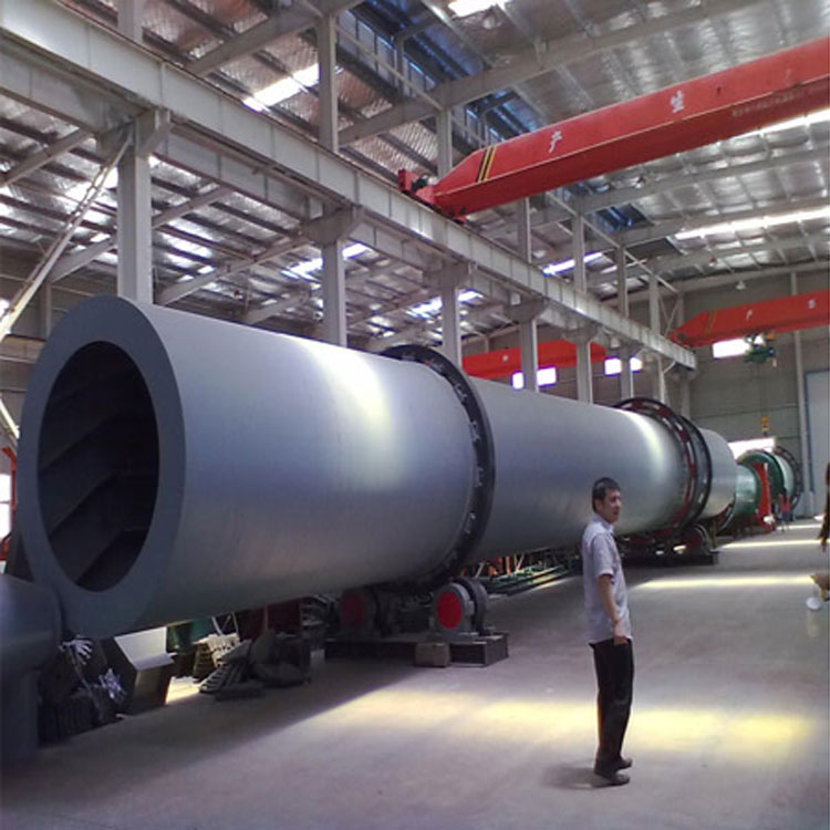
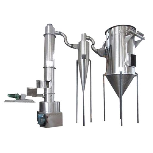
Wet materials are conveyed to the hopper via a belt conveyor or a bucket elevator, and then they enter the charging end through the hopper's feeding machine via a charging pipeline. The slope of the charging pipeline must be greater than the natural angle of repose of the material to ensure smooth flow into the dryer. The dryer is a rotating cylindrical drum slightly inclined from the horizontal line. Materials are added to the higher end, and the heat carrier flows in parallel with the materials into the drum. As the drum rotates, the materials are gravity-fed to the lower end. During their forward movement within the drum, the wet materials receive direct or indirect heating from the heat carrier, enabling them to dry. They are then discharged at the outlet end via a belt conveyor or a spiral conveyor. Scrapers are mounted on the inner wall of the drum, which function to lift and scatter the materials, increasing the contact surface with the airflow to enhance the drying rate and promote material movement. The heat carriers are typically hot air, flue gas, and so on. After passing through the dryer, the gas usually requires a cyclone separator to collect the material carried within it. To further reduce the dust content of the exhaust gas, it should pass through a baghouse or a wet scrubber before being released.
Features of Mining Drying Machines
1. High overload capacity, strong processing power, low fuel consumption, and low drying costs.
2. Utilizing a concurrent drying method, the flue gas and wet material enter the dryer from the same side, enabling a high evaporation intensity with the help of high-temperature flue gas, and the exit temperature of the dryer is low.
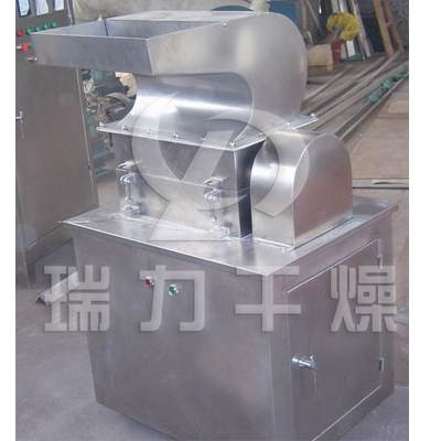
3. Utilizing a disassembling device, feeding device, discharge device, and cyclone dust removal device, we have effectively eliminated issues such as feed blockage, discontinuity, uneven feeding, and backflow in the dryer, thereby reducing the load on the dust removal system.
4. The dryer employs a "centering-type support wheel device," ensuring linear contact between the support wheel and the roller ring, thereby significantly reducing wear and power loss.
5. Features an open gear drive mechanism, offering a well-structured design, easy operation, long service life, and convenient maintenance.
During the drying production process, the most common operation is in a downstream manner, characterized by:
1. At the heat end of the drying machine, there's a significant temperature difference between the material and the hot gases, resulting in a rapid heat exchange process and easy evaporation of a large amount of moisture, making it suitable for materials with a high initial moisture content.
2. After sticky materials enter the drying machine, due to the easy evaporation of surface moisture, adhesion can be reduced, which is beneficial for material movement. When used to dry wet coal, it can prevent the dry coal from igniting by direct contact with high-temperature gases.
3. Low hot-end vacuum in downstream operation reduces the amount of air leakage into the drying process, which is beneficial for stabilizing the temperature and flow rate of the hot gases inside the dryer.
4. Feeding and coal supply are located at the hot end of the dryer, making the workshop layout more convenient.
5. The dryer discharge temperature for downstream operations is low, typically suitable for conveyance by a belt conveyor.
Mining dryer technical specifications
Specification (m) (Diameter × Length) | Tubular volume (m³) | Production Capacity (t/h) | Installation Angle (%) | Higher intake air temperature (℃) | Main Motor (kw) | Total Weight (t) |
| Φ1.2×8.0 | 9.0 | 1.9-2.4 | 3-5 | 700-800 | 7.5 | 9 |
| Φ1.2×10 | 11.3 | 2.4-3.0 | 3-5 | 700-800 | 7.5 | 11 |
| Φ1.5×12 | 21.2 | 4.5-5.7 | 3-5 | 700-800 | 15 | 18.5 |
| Φ1.5×14 | 24.7 | 5.3-6.6 | 3-5 | 700-800 | 15 | 19.7 |
| Φ1.5×15 | 26.5 | 5.7-7.1 | 3-5 | 700-800 | 15 | 20.5 |
| Φ1.8×12 | 30.5 | 6.5-8.1 | 3-5 | 700-800 | 18.5 | 21.5 |
| Φ1.8×14 | 35.6 | 7.6-9.5 | 3-5 | 700-800 | 18.5 | 23 |
| Φ2.2×12 | 45.6 | 9.7-12.2 | 3-5 | 700-800 | 22 | 33.5 |
| Φ2.2×14 | 53.2 | 11.4-14.2 | 3-5 | 700-800 | 22 | 36 |
| Φ2.2×16 | 60.8 | 13.0-16.2 | 3-5 | 700-800 | 22 | 38 |
| Φ2.4×14 | 63.3 | 13.5-16.9 | 3-5 | 700-800 | 37 | 45 |
| Φ2.4×18 | 81.4 | 17.4-21.7 | 3-5 | 700-800 | 37 | 49 |
| Φ2.4×20 | 90.4 | 19.3-24.1 | 3-5 | 700-800 | 45 | 54 |
| Φ2.4×22 | 99.5 | 21.2-26.5 | 3-5 | 700-800 | 45 | 58 |
| Φ2.6×24 | 127.4 | 27.2-34.0 | 3-5 | 700-800 | 55 | 73 |
| Φ3.0×20 | 141.3 | 30.1-37.7 | 3-5 | 700-800 | 75 | 85 |
| Φ3.0×25 | 176.6 | 37.7-47.1 | 3-5 | 700-800 | 75 | 95 |
| Φ3.2×25 | 201 | 42.9-53.6 | 3-5 | 700-800 | 90 | 110 |
| Φ3.6×28 | 285 | 60.8-76.0 | 3-5 | 700-800 | 160 | 135 |
Indirect Heat Transfer Drying Machine
| Bore Diameter × Bore Length - Item | Outer Diameter of Cylinder (mm) | Inner Tube Diameter (mm) | Tubular Length (m) | Tubular Volume (m³) | Body Slope | Feed Plate Type | Higher Intake Air Temperature (°C) | Dimensions (m) |
| Φ1.5×15m | 1500 | 500 | 15 | 20.27 | 3-5% | Lifting mechanism | 850 | 16.2×2.7×2.7 |
| Φ1.5×17m | 17 | 22.97 | 18.2×2.7×2.7 | |||||
| Φ1.5×19m | 19 | 25.68 | 20.0×2.9×2.9 | |||||
| Φ1.8×21m | 1800 | 650 | 21 | 35.91 | 3-5% | Lifting mechanism | 850 | 22.5×2.7×2.7 |
| Φ1.8×23m | 23 | 39.33 | 24.5×2.9×2.9 | |||||
| Φ1.8×25m | 25 | 42.75 | 26.5×2.9×2.9 | |||||
| Φ2.2×21m | 2200 | 800 | 21 | 58.10 | 3-5% | Lifting mechanism | 850 | ---- |
| Φ2.2×23m | 23 | 63.61 | ||||||
| Φ2.2×25m | 25 | 69.15 |