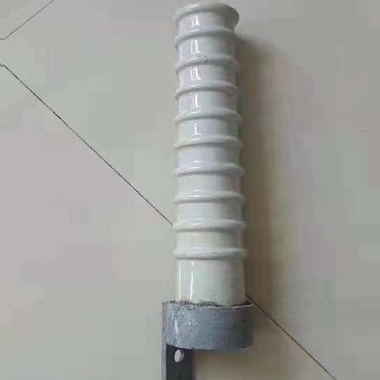


High voltage line porcelain cross arm insulator
I. Overview
Used for insulation and supporting wires in high-voltage overhead power lines with a nominal voltage of 35kV and below, a frequency not exceeding 100Hz, and an altitude not exceeding 1000m in three-phase power systems. The ambient temperature of the insulator installation location is -40 ℃ to+40 ℃.
Two structural characteristics
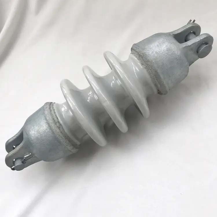
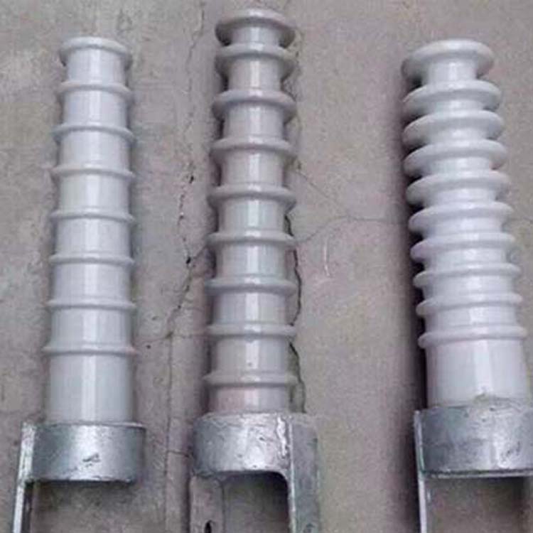
Ceramic cross arm insulator is a conical or cylindrical ceramic insulator structure that serves as both a cross arm and an insulator. In addition to having the same function of fixing wires and insulating against ground as ordinary line insulators, it can also completely or partially replace iron or wooden cross arms. This type of insulator was developed in China to save materials such as metal, cement, and wood for cross arms and meet the needs of rural power line construction. It can be installed horizontally or vertically, so compared with disc insulators or long rod insulators, it can also reduce the height of the tower and simplify the tower structure. Since a porcelain cross arm transmission line was put into operation in China in 1963, this type of transmission line has developed rapidly in the past few decades. Currently, 110kV and below transmission lines, especially 6-35kV transmission lines, have been widely promoted and adopted.
At the beginning stage of development, there are two types: pure ceramic and adhesive.
Pure ceramic structure refers to solid ceramic parts with mounting holes at the root. When in use, the mounting holes are threaded through the screws and compressed with a pressure plate. A cushion (such as asbestos cloth) should be placed between the ceramic and iron parts during compression, and a spring washer should be added to the pressure plate for compression. However, this structure has been abandoned due to its low strength and poor operational reliability.
The adhesive structure is composed of solid ceramic parts and flanges glued together with adhesive. The flanges are equipped with mounting holes for screws and nails to be installed. Ceramic crossarms with medium voltage and above voltage levels that are widely used are equipped with metal accessories (flanges). In order to buffer the impact force generated when the line breaks, the flange is also equipped with stabilizing screw holes. When the load exceeds the strength of the stabilizing screw, the stabilizing screw will cut off and the porcelain cross arm will rotate around the installation hole, thereby increasing the relaxation of the wire, reducing the tension of the wire, and avoiding insulator breakage or pole collapse accidents. Stable screws during normal operation can overcome the tension difference between the two sides of the wires that exists under normal circumstances. Pure ceramic roots do not have stable screws, and in this case, the frictional force at the installation site overcomes the tension difference between the two sides of the wire. When the wire breaks, it can also rotate around the installation hole. There is also an elastic pad (usually made of felt paper) between the flange of the adhesive structure and the end face of the ceramic part to reduce thermal stress. Flanges are generally cast from malleable iron or welded from steel plates, and the surfaces of metal accessories are all hot-dip galvanized. The adhesive is prepared by mixing not less than 42.5 grade Portland cement and quartz sand
There are two types of ceramic cross arm insulators: horizontal installation and vertical installation. There are two types of wire binding: direct binding and wire clamp fixation. If the insulator is installed horizontally and the wire is tied to the side groove of the porcelain piece head with thin metal wire, the insulator does not need to make a top groove at this time; If the insulator is installed upright, the wire is tied to the top groove of the porcelain piece. Therefore, if the top phase porcelain cross arm insulator is installed upright during operation, the manufacturer needs to produce a portion of the specifications with top grooves for this type of insulator. Another type of fixed wire is a ceramic piece with a connector at the head to clamp the wire.
The porcelain cross arm insulator in our country is actually a type of line column insulator that can rotate in case of an accident
Compared with ordinary line insulators of the same voltage level, the electrical and mechanical properties of porcelain cross arm insulators are characterized by:
(1) The insulation distance and creepage distance of the porcelain cross arm are relatively large, and the 50% full wave impulse flashover voltage and dry/wet power frequency flashover voltage are relatively high
(2) The porcelain body of the porcelain cross arm is relatively long and has low mechanical bending strength. Considering the safety and reliability factor, the allowable large load is generally smaller than that of ordinary line insulators of the same voltage level. Therefore, the porcelain cross arm is not suitable for lines with large wire cross-sections and block distances.
Compared with distribution lines installed with ordinary insulators, the main advantages of porcelain cross arm distribution lines are:
(1) By adopting a rotatable structure, the imbalance of wire tension during line breakage will cause the ceramic crossbar to rotate, effectively mitigating the escalation of wire breakage accidents;
(2) The insulation level and lightning resistance level of the line are relatively high, and the accident rate is low;
(3) Ceramic bodies are easily washed by wind and rain, have good self-cleaning properties, and will not break down, requiring minimal replacement and maintenance;
(4) Construction and installation are convenient, and the same height of the pole can increase the distance between the wire and the ground by about 0.3-2.2m;
(5) Save raw materials such as steel and wood, and can reduce the cost of a single tower by 10% to 50%.
3、 Model Description
JB/T 8179-1999 standard specifies (old model):
S - Ceramic cross arm insulator;
The numbers 1, 2, 3... after S are the design sequence numbers;
The number after "-" represents the rated voltage value, kV;
The number after "" represents the rated bending failure load value, kN。
GB/T 21206-2007 standard specifies (new model):
RA - Line column insulator used as a cross arm;
The number after RA represents the bending failure load value, kN;
The following letter E or J represents the external or internal adhesive installation of metal accessories;
The following letters T, C, and H respectively represent top tie type, vertically installed top clamp type, or horizontally installed top clamp type;
The suffix number represents the specified lightning impulse withstand voltage value, peak kV;
The letters N or L in the suffix represent standard and longer creepage distances, respectively.