


Service Scope:
1. Comprehensive pipeline engineering for laboratory centralized gas supply systems, including the full spectrum of installation and commissioning services: design, selection, product supply, maintenance, and technical support.
2. Installation of ultra-pure gas delivery systems, specialty gas cabinets (GC, GR), distribution boxes (VMB, VMP), and secondary piping construction services.
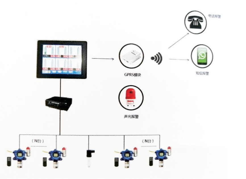
3. Gas pressure monitoring and alarm system, installation and debugging of gas concentration monitoring and alarm control systems.
4. Lab pure water piping system installation, lab wastewater treatment system design and installation.
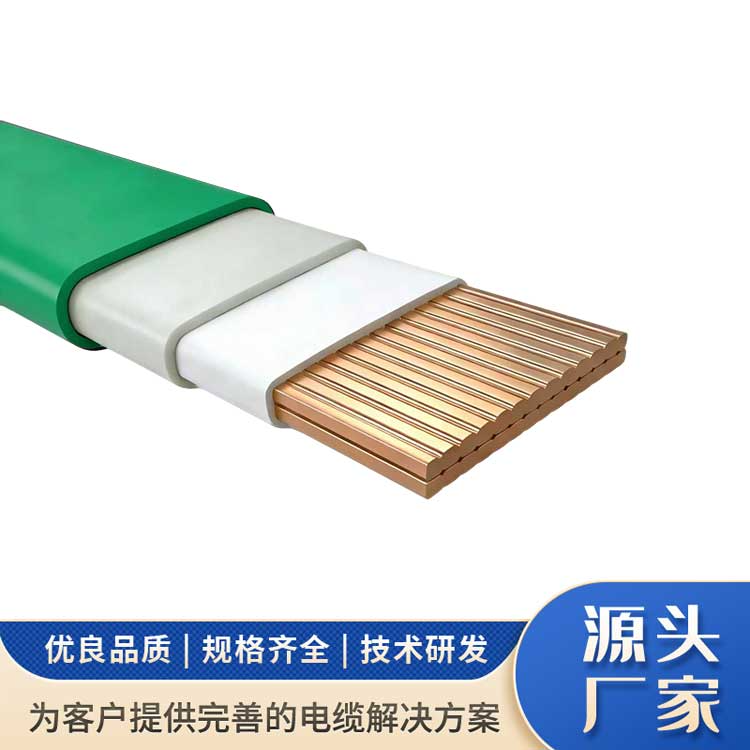
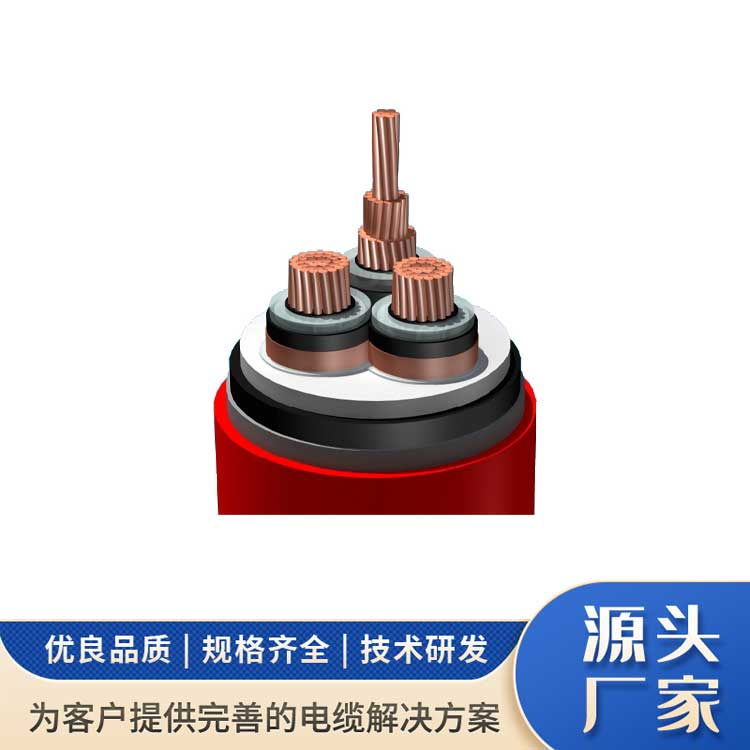
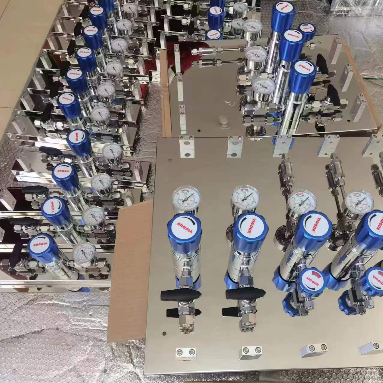
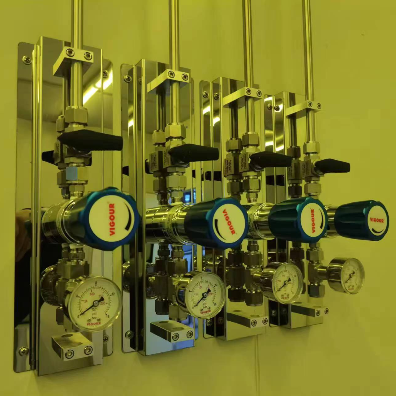
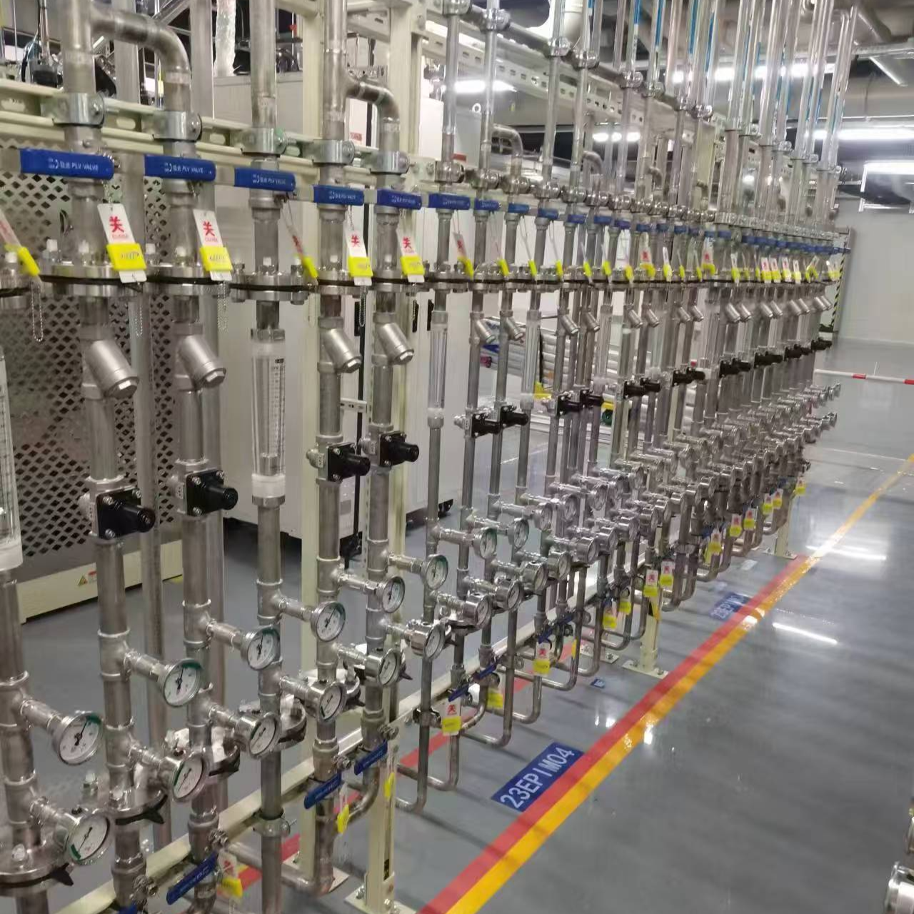
5. Valve Components: Automatic regulating and controlling equipment for various gas supply systems, gas regulators, valves of various stainless steel pipe grades (EP, BA), including diaphragm valves, ball valves, needle valves, safety valves, check valves, flame arresters, sleeve joints, precision filters, and various pressure gauges.
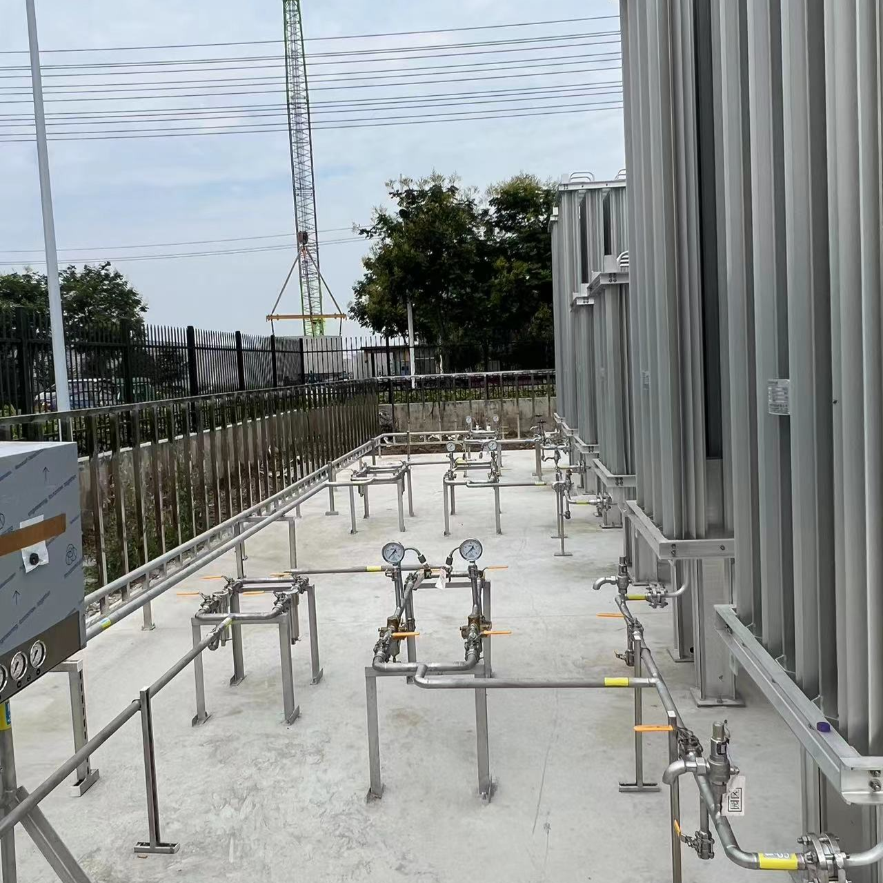
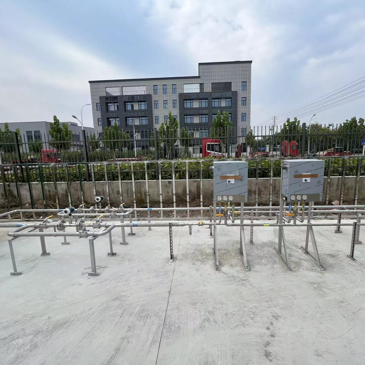
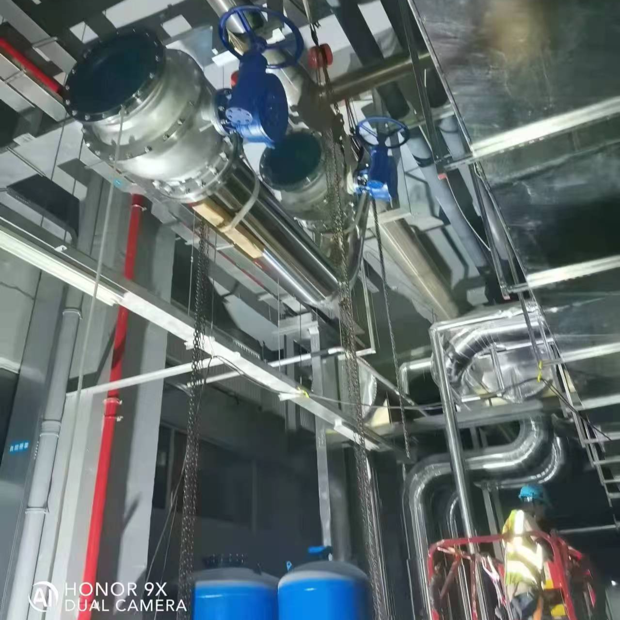
Gas Source Cylinder Room Design Description
• Utilizes a semi-automatic switching system to ensure continuous gas supply. Guarantees the continuity of experiments.
• Multi-bottle gas supply ensures sufficient gas usage.
• Cylinders are arranged in a cluster for easy refilling operations.
• No bottles in the lab, saving space and eliminating a hazard source.
• Equipped with a safety valve to ensure safe operation.
• Nitrogen blow-off and venting features ensure gas purity.
• Features low-pressure alarm, alerting users to replace the cylinder when the pressure drops below the operating level.
• The design of the combustible gas system includes a PLC control system, enabling联动 between the combustible gas alarm, emergency shutdown, and fan. Ensures gas safety usage.
• Different gases use different materials to ensure purity.
• Different connection methods (VCR, ferrule, welding) are used according to the type of gas.
• The high-pressure section is equipped with a high-pressure valve 1 to ensure safe gas usage.
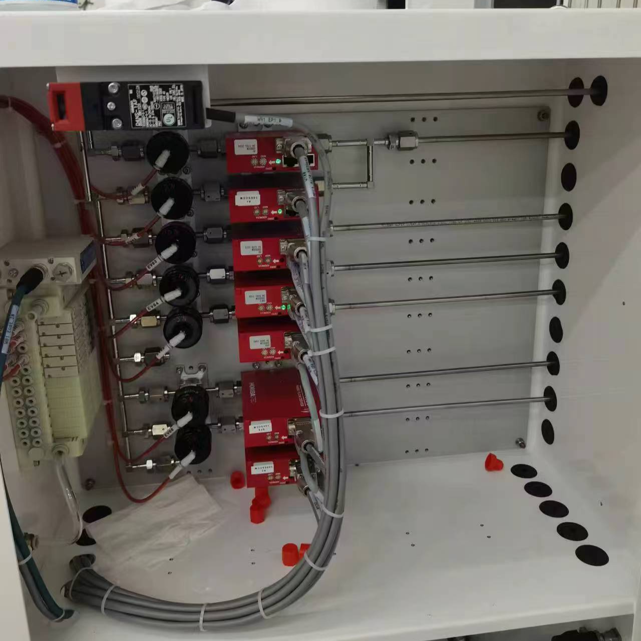
Monitoring System Design Description
• The gas cylinder room is equipped with gas concentration leak detectors and emergency shut-offs. In the event of harmful gas leakage, the concentration detection alarm will trigger both audible and visual alarms, and send a signal to the exhaust valve to activate the fan for air exchange, ensuring safe gas supply.
• Gas alarm uses 4~20mA signal and is explosion-proof level EX-1ICT6. Enhances safety level.
• All signal lines are made with 4-core shielded cables to prevent signal interference.
•PLC internal signal input terminals are all reserved, achieving expandability and allowing real-time display of concentration/pressure values.
• The unit is equipped with a touch screen that displays the same image as the host computer. It operates on Windows XP, offering ease of use.
Design based on technical specifications:
GB50235-2010 "Code for Construction of Industrial Metal Pipeline Engineering"
GB50184-2011 "Code for Acceptance of Construction Quality of Industrial Metal Pipeline Projects"
GB50236-2011 Code for Construction and Acceptance of Field Equipment and Industrial Pipeline Welding Engineering
JGJ 91-93 "Code for Architectural Design of Scientific Experimental Buildings"
GB50031-1991《C₂H₂Website Design Standards
GB50177-2005《H2Website Design Specifications
GB 50030-2007 "Code for Design of Oxygen Stations"
GB50029-2014 "Code for Design of Compressed Air Stations"
SH3063-1999 "Design Specifications for Detection and Alarm of Flammable Gases and Toxic Gases in Petroleum and Chemical Enterprises" - Laboratory existing conditions, requirements, and other relevant standards and specifications.
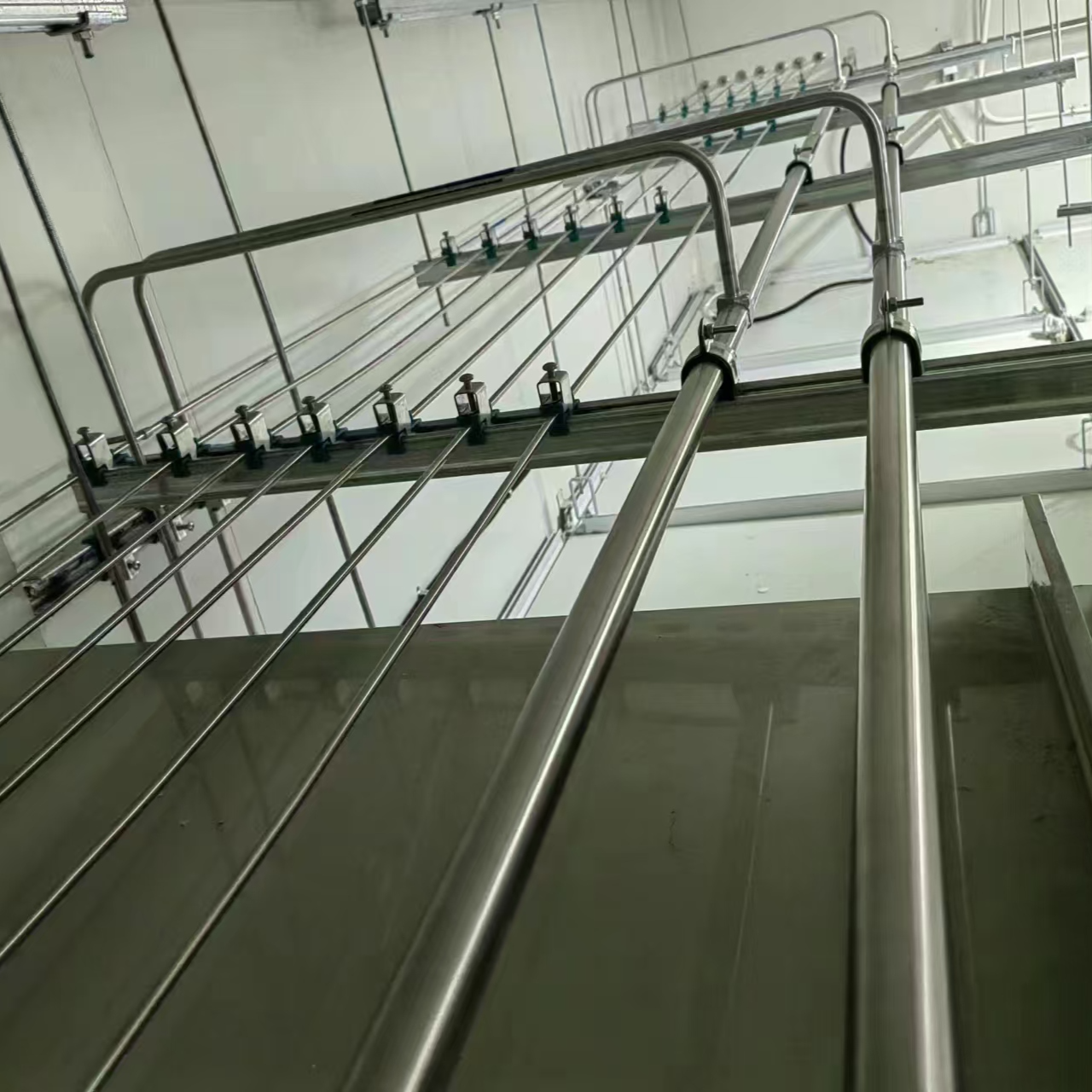
Functional Column/Pipe Chute Description
• All connecting pipelines are焊接 using digital welding technology, ensuring safe use. This layer has预留 openings in the pipeline shaft for unused gases, convenient for future gas line additions.
Flammable gases are equipped with flame arresters in the pipeline wells, enhancing safety coefficients.H2、C₂H₂、CH₄Valves for pneumatic control are designed to interface with PLCs. Each gas line is equipped with a floor main control valve.
Select different pipe sizes based on varying gas consumption.
• Gas pipeline support spacing should not exceed 1.5 meters. Determine the support distance based on the smallest internal diameter of the gas pipeline.
Design Instructions for Indoor Pipe Valves for Instruments
Each laboratory must have individual valve controls.
For instruments requiring separate pressure adjustment, a dedicated valve must be installed at the gas outlet point on the workbench to control it.
All gas export points are equipped with stainless steel valves and connected to pressure and flow regulators.
• The H2 is connected using a VCR-style fitting, while other gases are connected with a coupler.
• Rooms with combustible gases are equipped with combustible gas detectors linked to a PLC.
• Gas enters the main pipeline in the room, installation of a gas purification system can improve the purity of the gas.