


I. Application
Double-metal blade air coolers are mainly used for air cooling of generators and motors in the power industry. They are designed to reduce the temperature of the air cooling the generator, enabling its recirculation and achieving the goal of energy conservation and cost reduction.
II. Advantages
Compared to traditional spiral fin air coolers, the significant advantages of the bimetal (copper, aluminum) composite fin (rolled) air cooler are its larger surface area for heat dissipation (increased by 30%), higher cooling capacity (increased by 20-30%), and lower air resistance (reduced by 20%). Its performance is largely unaffected by the length of use, making it an ideal alternative product for spiral fin air coolers.
III. Working Principle:
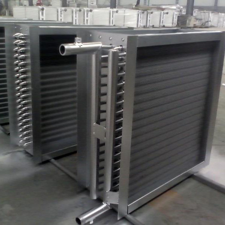
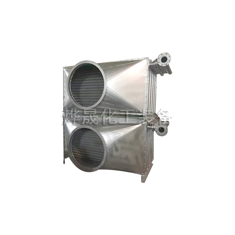
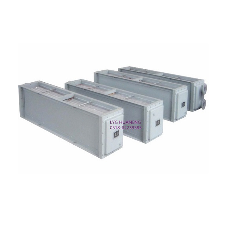
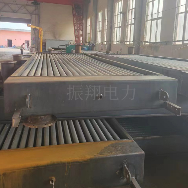
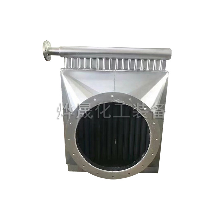
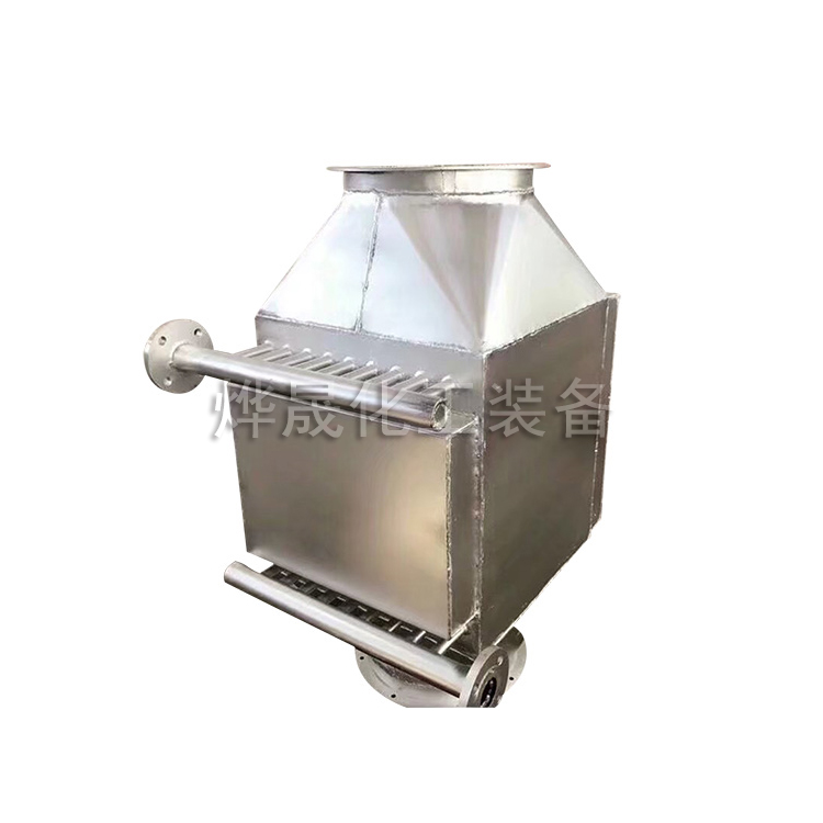
The air cooler principle consists of three main parts: the tube bundle, the fan, and the frame. The tube bundle includes heat pipes, tube boxes, side beams, and cross beams. It can be arranged in three basic forms: horizontal, vertical, and inclined (V-shaped). The horizontal arrangement ensures uniform heat area and air distribution, while the inclined arrangement positions the fan in the V-shaped space, minimizing the footprint and making the structure compact. To counteract the lower heat transfer coefficient on the air side, tubes with fins attached to the outer surface of the smooth tube are commonly used. The finned tubes, acting as heat pipes, can increase the heat transfer area. They are arranged in layers and connected to the tube box at both ends using welding or胀接 methods. The tube bundle typically consists of 3 to 8 rows of tubes. The tube bundle series has dimensions up to 12 meters long. The outer diameter of the smooth tubes is 25 mm and 38 mm, with the fin thickness usually between 12 to 15 mm. The width of the tube bundle ranges from 100 to 3000 mm.

Finned tubes are components of air coolers, and their form and material directly affect the equipment's performance. Tubes can be made from carbon steel, copper, aluminum, and stainless steel; the fin material is determined based on the application environment and manufacturing process, with industrial pure aluminum used, and copper or stainless steel also employed under high corrosion requirements or special manufacturing conditions. Fins can be arranged horizontally or vertically. Basic forms of finned tubes include: coiled, inserted, rolled, sleeve, welded, elliptical tube, and turbulent (including radial, slotted, and corrugated shapes, etc.). The tube box structure includes flanged, plug, and manifold types. The former is generally used for low-pressure applications, while the latter two are for high-pressure applications. To accommodate the thermal expansion of the tube bundle, the end tube box is not rigidly fixed, allowing for displacement along the tube length. The fan used in ventilation systems is typically an axial flow fan.
IV. Air Cooler Ventilation Method:
There are two types of ventilation for air coolers: blowing and extracting.
① Blower-type air cooler: Air flows through the blower and into the tube bundle.
② Draft-type Air Cooler: Air flows through the tubes and into the ventilator.
The former has more economical operator costs, generates beneficial turbulence for heat, and is more energy-efficient. The latter features uniform airflow distribution, which is advantageous for precise temperature control, low noise levels, and represents the direction of development.
The outlet temperature of the hot fluid needs to be controlled by adjusting the air volume passing through the bundle, i.e., by adjusting the angle of the blades, the speed of the fan, and the opening degree of the louver.
For fluids prone to freezing and condensation in winter, methods such as hot air recirculation or steam heating can be used to regulate the outlet temperature of the fluid.
V. Technical Specifications
| Product Model | Total Capacity: KW | Single machine external dimensions: Length x Width x Height in mm | Quantity | Waterway numbers | Cooling Water Flow: m³/h | Airflow m³/h | Water resistance pressure drop x 10 Pa | Airflow Resistance Pressure Drop: Pa | Inlet Water Temperature (°C) | Airflow Temperature (°C) | Design Pressure: MPa | Test Pressure MPa | Single |
| KLZ52-1202 | 36 | 1478x420x436 | 1 | 2 | 23 | 1.5 | 0.408 | 300 | ≤33 | ≤40 | 0.2 | 0.6 | 270 |
| KLZ 124-2250 | 140 | 2575x886x420 | 1 | 60 | 6.1 | 0.757 | 225 | 700 | |||||
| KLZ90-3724A | 700 | 3971x510x560 | 4 | 200 | 18 | 1.51 | 300 | 850 | |||||
| KLZ90-3724B | 800 | 3971x510x560 | 5 | 250 | 24 | 1.49 | 850 | ||||||
| KLZ52-2740 | 360 | 2072x436x420 | 4 | 100 | 13 | 0.872 | 403 | ||||||
| KLZ52-2020A | 125 | 2252x436x420 | 2 | 46 | 4 | 0.581 | 450 | ||||||
| KLZ52-2020B | 180 | 2252x436x420 | 3 | 70 | 8 | 0.599 | 450 | ||||||
| KLZ148--1485 | 125 | 1830x399x1075 | 1 | 3 | 40 | 48 | 0.652 | 225 | 710 | ||||
| KLZ78-2540 | 200 | 2860x514x410 | 4 | 2 | 45 | 45 | 1.17 | 251 | ≤30 | 0.8 | 820 | ||
| KLZ54-4680 | 250 | 5618x530x310 | 6 | 252 | 28 | 0.87 | 103 | 920 | |||||
| KLZ94-2730 | 560 | 3046x630x650 | 4 | 230 | 204 | 1.46 | 320 | 0.6 | 930 | ||||
| KLZ196-1700 | 160 | 2023x500x1923 | 4 | 4 | 240 | 20 | 1.98 | 113 | ≤33 | 1054 | |||
| KLZ105-2925 | 1100 | 3298x590x420 | 8 | 2 | 400 | 45 | 4.90 | 118 | 0.8 | 1350 |
The above air cooler parameters are for reference only, the actual design specifications apply!
Section 6: Order Instructions:
Cooling Water Volume
2. Existing Space
3. Inlet Water Temperature
Airflow
5, Total Capacity: Less than kW