


I. Main Technical Specifications
1. Workbench Width: 300 mm
Slice Width: Not greater than 100 millimeters
3. Slice Thickness: 1~12 mm
4. Material Thickness: 20mm
5. Motor: Y100L-8; 1.1 kW, 710 rpm; 380V
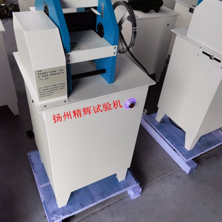
6. Dimensions (Length x Width x Height): 640×500×1050 mm
7. Net Weight: 215 kg
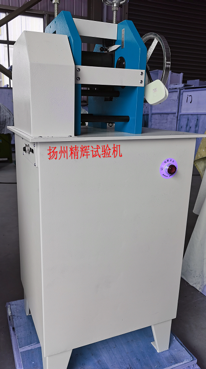
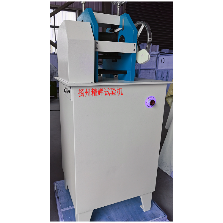
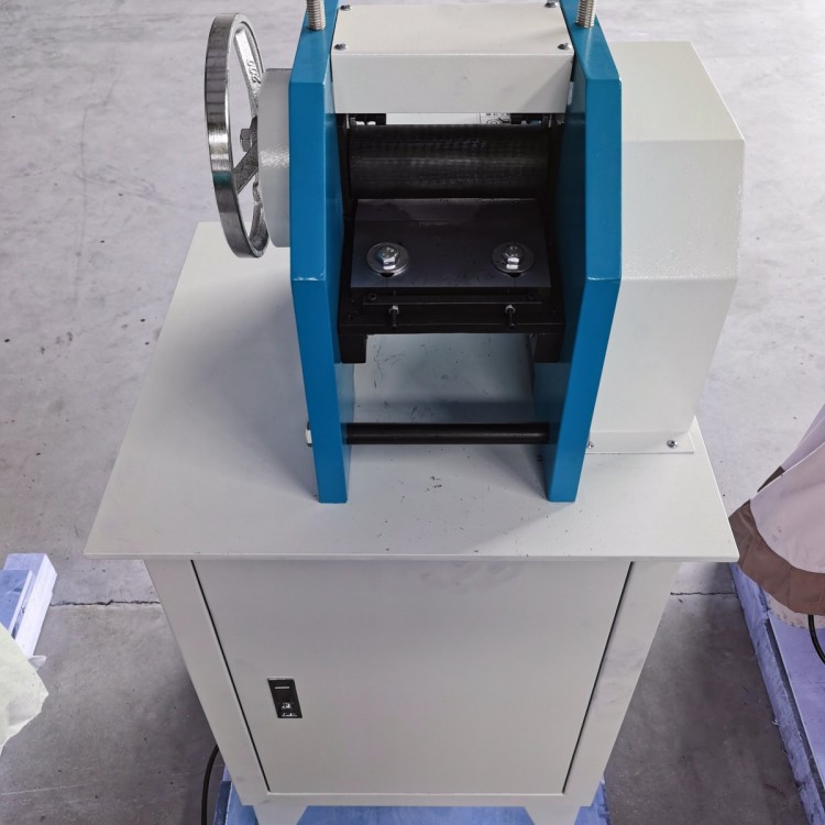
II. Structure and Usage
Rubber ShredderThe assembly is composed of parts such as the fuselage, transmission, adjustment, and control, with each part's structure and usage described as follows:
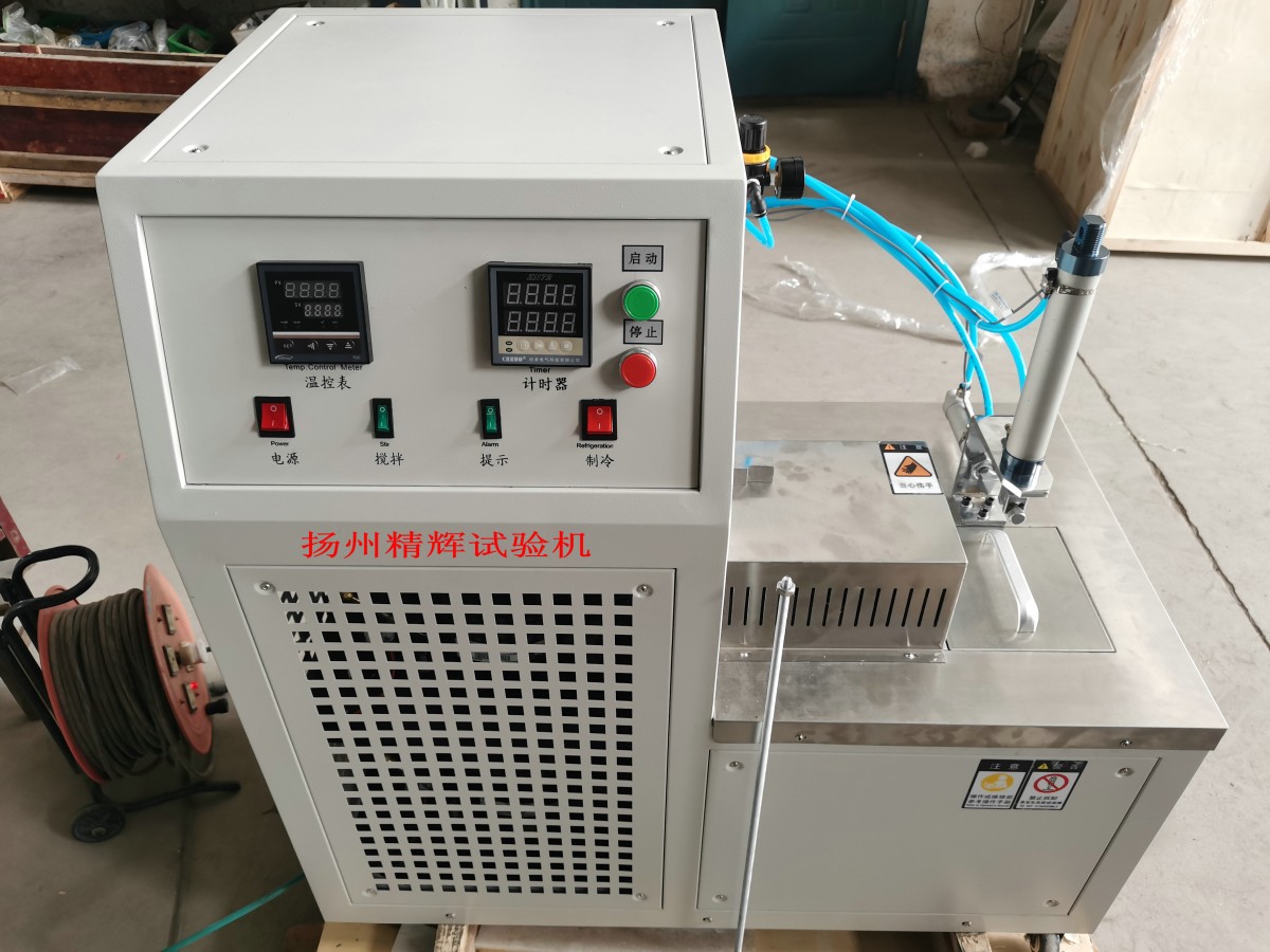
1. Frame and Transmission: The lower part of the frame serves as the base, housing the motor and electrical accessories, with start and stop switches for the motor on the exterior. The upper part of the frame is the working section, equipped with left and right frames, workbench, clamping shaft, feeding shaft, and adjustment mechanisms, etc.
Rubber ShredderAt work, press the "Start" switch to begin the slicer's operation; press the "Stop" switch to halt the slicer's operation.
The transmission is driven by an electric motor, which rotates the drive shaft through main and auxiliary belt pulleys. Gears mounted at both ends of the drive shaft drive the upper and lower feeding shafts to rotate, and then the gears on the upper feeding shaft rotate the tension shaft simultaneously.
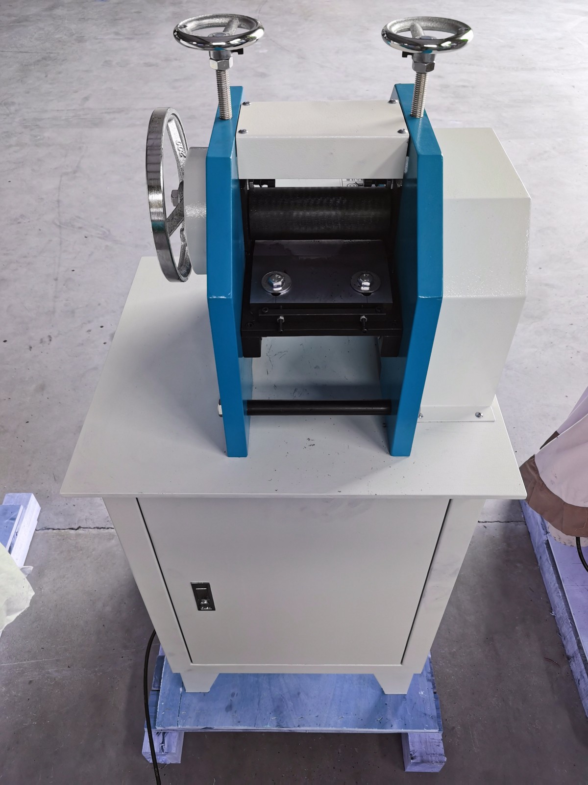
2. Manipulation and Adjustment
The handwheel on the right is generally used during debugging and rotates freely during operation.
Turn the adjusting handwheel above the motorized frame to adjust the pressing shaft and the upper feeding shaft to rise (or lower) to achieve the desired slice thickness.
The handwheel adjusts the thickness by 1mm per full turn.
Section 3: Installation and Maintenance
1. Remove the anti-rust oil from the exposed surfaces and inspect all mechanical parts and electrical components for loosening, loss, or damage due to shipping.
2. Connect the power and ground wire safely, ensuring the motor's rotation direction aligns with the arrow on the belt pulley cover.
3. Check the tension of the V-belt. If it's not appropriate, open the rear cover and adjust the motor base connection nuts with the mounting base.
4. Before turning on the slicer, add lubricating oil at the locations shown in the diagram (positions 1, 2, 3, 4, 5, 6, 7 should be lubricated at least twice per shift, and positions 8, 9, 10, 11, 12, 13 should be lubricated at least twice per week). Apply a small amount of grease to the drive gear surfaces. Ensure that the upper and lower feeding shafts are free of oil stains, and check that all parts operate smoothly.
5. In addition to regular oiling and lubrication, maintain the machine's cleanliness, pay attention to maintenance and operational safety, and never operate with gloves or manually push or pull to assist with feeding materials.
6. In case of abnormal operation or damage to the machinery, immediate repair should be conducted.