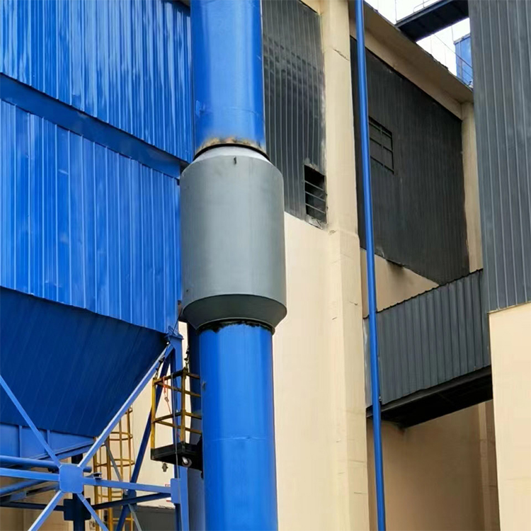

The LY type cooler is a turbo oil cooling unit used in conjunction with steam turbines in power systems. This type of cooler is a shell and tube design, utilizing recirculated water as the medium for heat exchange, thereby ensuring that the oil temperature at the bearing inlet reaches the specified level, enabling the unit to operate normally.
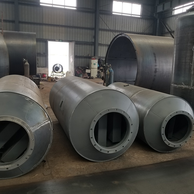
The main components of the LY type cool oil cooler include the upper and lower water chambers, shell tube system, and oil filling pipeline. The shell is equipped with inlets and outlets for water, oil, drain pipes, oil drain pipes, exhaust pipes, and a temperature gauge bracket.
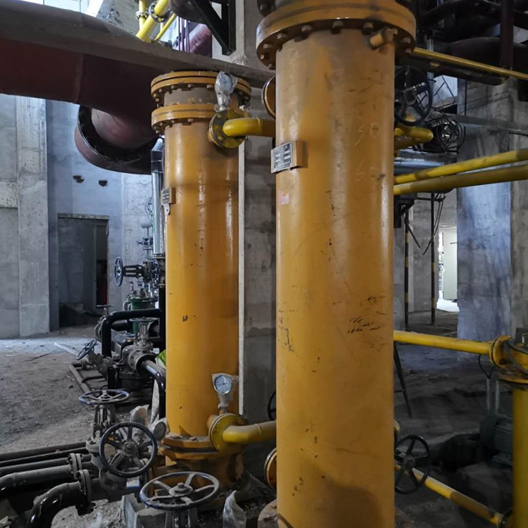
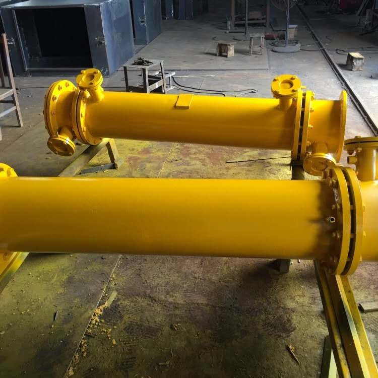
The cooling water flow is typically a dual-loop system, and the cooler is usually mounted vertically, but can also be installed horizontally (select a horizontal cooler).

II. Key Features of the Cool Oil Cooler
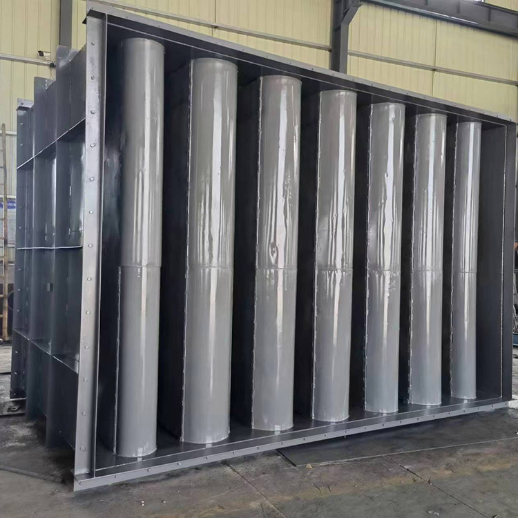
1. The cooler utilizes copper tubes as heat exchange elements, featuring high thermal conductivity, large heat exchange area per unit length, and high heat transfer capacity.
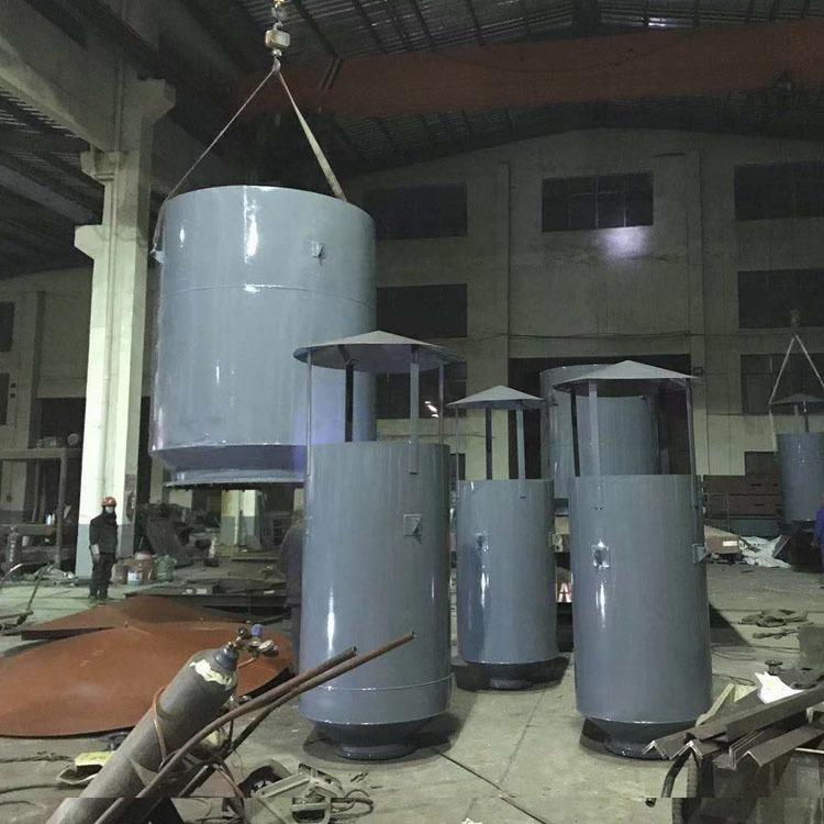
2. The cooler features a rational structure, maintaining stable oil outlet temperature over a wide temperature range, and exhibits excellent resistance to sudden temperature changes and vibrations.
3. The cooler assembly structure is reliable; cooling water will not enter the steam turbine unit.
4. The fin of the cooler is smooth with no burrs, no creases, and is resistant to dust and scale buildup, featuring low fluid resistance.
Section 3: Selection of Coolant Coolers
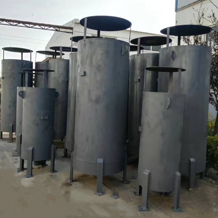
When selecting a cold oil cooler, please specify the cooling area. The cooling types include LY type tubular (commonly used) and LYC type finned. The heat exchange cooling tubes are generally made of purple copper, but can also be made of stainless steel or brass as per the customer's requirements.
Section 4: Advantages of Cold Oil Coolers
To ensure sufficient cooling for the turbine oil during operation, the twin cooler system consists of two identical oil coolers and a three-way valve, allowing one to operate while the other is on standby. In cases where the cooling effect is poor due to high unit oil temperature or high incoming water temperature, both coolers can be used simultaneously. Additionally, if cleaning or maintenance of the oil cooler is required during operation, the standby cooler can be activated without the need to shut down the equipment.
The steam turbine generator set is operating normally, but some work is consumed due to bearing friction. The cooler converts this into heat, raising the temperature of the bearing lubricant. If the oil temperature becomes too high, the bearings may soften, deform, or suffer burn damage. To ensure the bearings operate correctly, the lubricant temperature must be maintained within a specific range. Generally, the oil temperature entering the bearings should be between 35-45°C, and the oil outlet temperature rise should be around 10-15°C. Therefore, the oil discharged from the bearings must be cooled before being recirculated for lubrication. The cooler is designed to cool the main engine lubricating oil. The higher-temperature lubricant and lower-temperature cooling water exchange heat in the cooler, and the oil temperature is controlled by adjusting the flow of the cooling water (due to the higher rotor temperature, especially on the high-pressure cylinder inlet side, the cooler shaft also transfers heat outward, so the lubricant also cools the shaft neck).
V. Advantages and Disadvantages of Series and Parallel Arrangements of Coolant Recirculators
The advantages of series operation of cool oilers include: excellent cooling effect and uniform oil temperature.
2. Drawbacks of series operation of cool oil coolers: significant oil pressure drop, unable to isolate during oil leakage.
3. Benefits of parallel operation of oil coolers: minimal pressure drop, easy isolation, and the ability to service one set during operation.
4. Drawbacks of parallel operation of oil coolers: poor cooling effect, uneven oil temperature.
Section 6: Process requirements for replacing stainless steel pipes in cool oil exchangers
1. Preparation of new stainless steel tubes for the cool oil cooler: Cut the stainless steel tubes that have passed inspection to fit the dimensions of the cool oil cooler, ensuring the tubes are 4-5mm longer than the tube plate. Remove burrs from both ends of the stainless steel tubes, smooth the expansion section, and perform tempering treatment approximately 50mm from each end.
2. Cold Oil Coolers, Remove Old Stainless Steel Pipes: Use a special semi-circular triangular chisel to remove them. Be careful not to damage the tube plate. Remove the stainless steel pipes completely. After pulling out the old stainless steel pipes, clean the tube plate holes thoroughly. Sand them smooth with fine sandpaper and wipe off the dust with a cloth.
3. New Tube Installation and胀口in Coolant Exchanger: After the tube plate and stainless steel tubes are ready, new stainless steel tubes can be installed. Be cautious not to apply excessive force or twist, align them with the correct hole positions, ensuring that the exposed ends of the new tubes are equal. The diameter of the tube plate holes should be slightly larger than the tube diameter, approximately 0.5mm, but not too large or too small. Once the stainless steel tubes are in place, use a胀管器 to胀口. During胀管, avoid excessive force or speed, and the length of the胀管 should be two-thirds of the tube plate thickness, but not thicker than the tube plate. After胀管, use a punch to chamfer the ends.
4. When replacing the cold oil cooler with stainless steel tubes, replace them half by half. Disassemble half, replace them, and then disassemble the other half.
Chapter 7: Main Reasons for Overcooling of Condensate from Cold Oil Coolers
1. Air accumulation on the condenser steam side reduces the steam partial pressure, thereby lowering the condensate water temperature.
2. The condenser's water level is too high during operation, flooding some cooling water pipes and causing excessive supercooling of condensate.
3. Poorly arranged or excessively dense condenser cooling water piping results in the formation of a water film on the exterior of the condensate cooling water pipes. The outer layer of this water film approaches the saturation temperature of steam, while the inner layer is in close contact with the exterior of the stainless steel pipes, thus being close to or equal to the cooling water temperature. When the water film thickens and hangs down as droplets, the temperature of these droplets is the average temperature of the water film, which is obviously lower than the saturation temperature, thereby causing supercooling.
Section 8: Working Principle of Cold Oil Cooler
Cooling water enters the cooler through the top cover and flows through the small tubes inside the cooler. Countless tiny cooling water pipes are fixed by baffles inside the cooler, creating several small compartments. The lubricant flows in an S-shape around the cooling water pipes, increasing the effective heat exchange area and enhancing the cooling effect. At the bottom of the cooler, a cooling water chamber is formed. The lubricant and cooling water are separated and sealed by two O-rings (grommets) and a copper bed.
Section 9: Analysis of Cold Oil Cooler Failure Causes
During the operation of the unit, the bottom end covers of the coolers for #1, #2, #5, and #6 units have repeatedly experienced leaks or oil leaks, particularly during startup or shutdown processes, with frequent occurrences of the fault. The isolation between the oil and water in the coolers, as well as the leakage of oil and water, depend entirely on two O-rings. If either of the O-rings is damaged or displaced, causing a change in the gap, leakage is inevitable. Since the sealing surface of this O-ring is on the left and right sides rather than the traditional top and bottom, increasing the clamping force of the flange bolts does not reduce the leakage amount once a leak occurs.
After analysis, the following reasons have been summarized for the easy change and damage of O-ring gaps.
1) During the start-up or shutdown of the unit, pressure fluctuations often occur on the oil side and water side of the cooler, causing the O-ring seal to shift and resulting in leakage.
2) During installation, if the cooler is installed off-center internally, it will cause an abnormal gap in the O-ring seal. During operation, any slight pressure fluctuations (on the oil or water side) can lead to leakage.
3) During each maintenance process, when replacing the O-ring, due to the limited space at the bottom end cover, installation is often cumbersome, leading to the O-ring being crushed by the copper bed and subsequently causing leaks. After each maintenance, the probability of leakage on the water side is higher than that on the oil side, further proving that the current design is not conducive to maintenance and ensuring maintenance quality.
Ten: Feasibility Analysis of Technical Renovation for Coolant Cooler
Between the bottom end cover of the oil cooler and the connecting flange of the middle barrel of the oil cooler, an expanded polytetrafluoroethylene pad is added. On top of the original sealing surface that was not convenient, two additional sealing surfaces are added. Due to the better flexibility of polytetrafluoroethylene material compared to copper pads, this meets the requirement of increasing the sealing performance by relying on the clamping force of the flange bolts. The difficulty in implementing this measure is significantly less than that of other measures.
Eleven: Economic Analysis of Technical Retrofit for Coolant Heat Exchangers
1) Each time a cold oil cooler leaks, repairs are typically conducted during either major or minor maintenance periods. During the period of operation with the injury, additional cleaning tasks for leaked oil and water are required, which increases the workload for the team.
2) The cold oil cooler end cover is large in volume and has limited maintenance space, requiring five people to work simultaneously every time an O-ring is installed, resulting in significant labor costs for each maintenance session.
3) Replacing O-rings during maintenance often results in a significant amount of consumables, which increases maintenance costs.
Through the above analysis, it can be proven that the necessity and feasibility of technical modification for the cooler are evident, as well as the economic benefits that can be gained after the modification is implemented. During the modification, a gradual approach can be adopted, utilizing the scheduled maintenance of the units, to progressively modify the coolers of Units #1, #2, #5, and #6. Upon completion, it is certain to yield corresponding economic benefits and save on equipment maintenance and repair costs.
Twelve: Order Instructions
Oil Cooler (Oil Cooler) Order Instructions
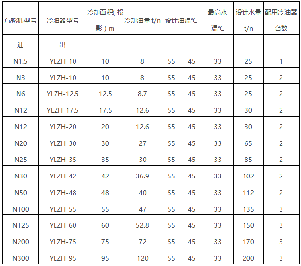
1) Turbine Generator Set Model
2) Coolant Oil Quantity
3) Oil Cooler Cooling Area
Turbine unit model
Condensate Turbine Coolant Performance and Specifications
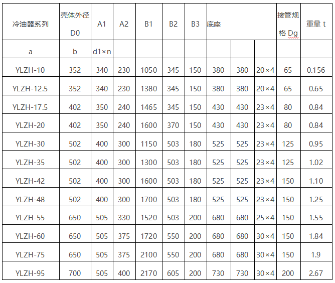
Product Dimensions