


Carrie30HXCEngine unit alarm code-Easier text search for mobile internet access
Carry Air30HXCScrew-type chilled water/Pump unit alarm code text formatting for easy online lookup via mobile phones, facilitating on-site maintenance and troubleshooting.15.4 Alarm Code - Description of Alarm Reason - Control System Action - Reset Type - Cause of Issue
1. Cold water intake temperature sensor failure: Exceeds sensor measurement range-40-118Parking, if the sensor measures a normal temperature, the alarm will automatically reset. Temperature sensor wiring fault or cable damage.2. Cold water outlet temperature sensor malfunction: As above, stop, as above, as above.
3. Cooling Water Inlet Temperature Sensor Failure: As above, no action, information display as above, as above.
4. Cooling Water Outlet Temperature Sensor Failure: As above, no action during refrigeration, stop during heating, as above, as above.
5. Hot Water Supply Temperature Sensor Fault: As above, no action, information display as above, as above.
6. Hot Water Recovery Cooling Water Outlet Temperature Sensor Fault: As above, no action, information display as above, as above.
7. Outdoor Temperature Sensor Fault: As above, based on the progress of the unactivated outdoor temperature sensor, as above, as above.
8. CHWS Main/Unit temperature sensor failure: As above, main/Disengaging from aircraft mode, as above, as above.
9. CompressorA1 Exhaust Temperature Sensor Failure: As above, compressorA1Parking, as above, temperature sensor, solenoid valve, motor cooling or wiring fault.
10. CompressorA2 Exhaust Temperature Sensor Failure: As above, compressorA2Parking, as above, as above.
11. CompressorB1 Exhaust Temperature Sensor Failure: As above, compressorB1Parking, as above, as above.
12. CompressorB2 Exhaust Temperature Sensor Fault: As above, compressorB2Parking, as above, as above.
13. 0-10V Direct current external signal fault: Signal out of bounds.1-Corrected-No use of2-Energy Limit-Invalid, automatic, input failure or wiring fault.
14. LoopAExhaust Pressure Transmitter Fault: Measurement Signal=0V dc LoopA Parking, if the sensor measures the temperature back to normal and the alarm is automatically corrected, the pressure transmitter is malfunctioning or there is a wiring fault.
15. LoopBExhaust Pressure Transmitter Fault: As above, circuitB Parking as above. Same as above.
16. LoopASuction Pressure Transmitter Fault: As above, circuitA Parking as above, as above.
17. LoopBSuction Pressure Transmitter Fault: As above, LoopB Parking as above, as above.
18. CompressorA1 Hydraulic pressure sensor failure: As above, compressorA1 Parking as above. As above.
19. CompressorA2 Hydraulic Pressure Sensor Failure: As above, compressorA2 Parking as above, as above.20. CompressorB1 Hydraulic Pressure Sensor Failure: As above, compressorB1 Parking as above, as above.
21. CompressorB2 Hydraulic Pressure Sensor Failure: As above, compressorB2 Parking as above, as above.
22. EconomizerA1 Pressure Transmitter Failure: As above, the loop with economizer unitAParking, No then compressorA1Parking, as above, as above.
23. EconomizerA2 Pressure Transmitter Failure: As above, compressorA2 Parking as above. As above.
24. EconomizerB1 Pressure Transmitter Failure: As above, circuit of economizer unitBParking, no then compressorB1Park, as above. As above.
25. EconomizerB2 Pressure Transmitter Fault: As above, compressorB2 Park, as above. As above.
26. LoopARemote condensate exhaust pressure transmitter failure: As above, no action, as above, as above.
27. LoopBRemote condensate exhaust pressure transmitter failure: As above, no action, as above, as above.
28. LoopAHot Recovery Mode Cooling Water Flow Fault: As above, the unit starts in standard cooling mode, automatically, as above.
29. LoopBHot Recovery Mode Cooling Water Flow Fault: As above, the unit starts in standard refrigeration mode, automatically
30. WithSCPM A1 PCB Communication LostCPM A1 PCB unresponsive, compressorA1Parking, automatic, wiring address fault, or circuit board damage
31. Please provide the Chinese content that needs to be translated into American English.SCPM A2 PCB Communication LostCPM A2 PCB unresponsive, compressorA2 Parking Automatic, same as above.
32. WithSCPM B1 PCB Communication LostCPM B1 PCB unresponsive, compressorB1 Parking Automatic, Same as above
33. WithSCPM B2 PCB Communication LostCPM B2 Printed circuit board unresponsive, compressorB2 Parking Automatic, Same as above
34. WithEXV PCB Communication LostEXV The4 DO PCB unresponsive, unit stops automatically, same as above35. With fan circuit board#1 Losing Communication [Not Used]: Control4 Blower fan4DO PCB unresponsive; if the fan speed level is below3So, will there be parking and how about the return route?AParking, automatic, as above.36. With fan circuit board#2 Lost Communication [Not Used]: LoopB The circuit board controlling the blower stages is unresponsive, the loopB Parking Automatic - Same as above
37. With1# 4 AI-2 AO PCB loses communication [Not in Use]: PCB is unresponsive; assume the unit will stop if operating in heating mode or using the fan speed controller or water valve assembly. Then it's just an information, automatic communication line address fault or PCB damage.
38. WithNRCP If communication is lost with the board, it will not respond, such as when the unit is in the heat recovery mode. If the board damage is detected again.
Please provide the Chinese content you would like translated. Engine unit shutdown panel Automatic Correction
39. C/clock Board failure: No response from circuit board; shutdown, as above, communication line address failure or circuit board damage
40. Control box temperature controller failure or phase reversal: sensor overheating, shutdown, manual, poor ventilation in control box
41. Emergency Stop ReceivedC Parking command shutdownC/Automatic Control Network
42. Factory Initial Setup: All factory parameters to be set0 Engine assembly fails to start, automatic, no factory settings
43. Illegal factory initial setup
43-1 CompressorA Excessive cooling capacity
43-2 Compressor set upB2 Without settingB1
43-3 Water-cooled unit with fan arrangement
43-4 Fan is not set
43-5 Hot recovery setup or hot recovery sensor setup error; Factory settings; Unit cannot start; Automatic; Factory settings error
44. LoopA Excessive exhaust pressure, only running at first-stage loading, with saturated condensing temperature exceeding the upper limit, circuitA Parking10 Auto-correct after minutes, sensor/High-pressure switch failure: Condensate pipe blockage or excessive cooling water intake temperature
45. LoopB Excessive exhaust pressure, operating only at the first stage upload while the saturated condensation temperature exceeds the upper limit, circuitB Parking10 Auto-correct after minutes, sensor/High-pressure switch fault: Condensate pipe blockage or excessive cooling water intake temperature
46. CompressorA1 Fuel supply solenoid failure: Before the fuel supply solenoid opens, the oil pressure after the oil pump starts-Economizer pressure is greater than17 kPaCompressorA1 Not operational, manual fuel solenoid valve is damaged
47. CompressorA2 Fuel supply solenoid failure: As above, compressorA2 Not allowed to start, manual as above
48. CompressorB1 Fuel supply solenoid failure, as above, compressorB1 Not allowed to start, manual as above
49. CompressorB2 Fuel supply solenoid failure, as above, compressorB2 Not allowed to start, manual as above
50. CompressorA1 Pre-start hydraulic alarm activated.3 The pre-lubrication process oil pump did not increase the oil pressure to an adequate level, compressorA1 Not permitted to start, manual, low oil level, oil pump supply solenoid or oil pressure sensor failure
51. CompressorA2 Pre-start hydraulic alarm as above, compressorA2 Not allowed to start, manual as above
52. CompressorB1 Pre-start hydraulic alarm as above, compressorB1 Not allowed to start, manual as above
53. CompressorB2 Pre-start hydraulic alarm as above, compressorB2 Not allowed to start, manual as above
54. LoopA Oil level switch malfunction: The oil level switch contacts are open during operation.A Parking manual, oil level switch malfunction or insufficient oil filling
55. LoopB Oil level switch disconnected as above, circuitB Parking Manual, as above
56. LoopA Low saturation suction temperature, saturation suction temperature lower than frost point setting*-3.3,3 Minute, circuitA Parking, Manual, Low Refrigerant Charge, Dull Filter Clogging, Electronic Expansion Valve Fault, Evaporation Pressure Transmitter Failure, Low Cold Water Flow, Low Cold Water Temperature
57. LoopB Low saturation suction temperature as above, return circuitB Parking Manual, as above
58. LoopA High saturation suction temperature Operation90 Seconds later, the saturated suction temperature exceeds12.8AndEXV Degree of opening less than1%LoopA Manual Parking Electronic Expansion Valve Fault in Evaporation Pressure Transmitter - High Evaporation Temperature
59. LoopB High saturated suction temperature, as above; return circuitB Parking Manual, as above
60. LoopA Low exhaust gas superheat continuously10 Minute overheat less than2.8LoopA Parking Manual Emission Temperature Sensor,Exhaust Pressure TransmitterEXV Or economizer failure
61. LoopB Low exhaust gas superheat as above, recirculationB Parking Manual, as above
62. CompressorA1 Exhaust Pressure-Hydraulic pressure exceeds the set value, pressure difference is greater than340 kPaOver6 Instant
Compressor A1 Parking, Manual, Oil filter clog, fuel supply solenoid or check valve failure
63. CompressorA2 Exhaust Pressure-Oil pressure exceeds the high set value, as above压缩机A2 Parking Manual, Same as above
64. CompressorB1 Exhaust Pressure-Hydraulic pressure exceeds the set value, as above, compressorB1 Parking Manual, as above
65. CompressorB2 Exhaust Pressure-Hydraulic pressure exceeds the high set value, as above, compressorB2 Parking Manual, Same as above
66. Lost communication with system administrator.C Connection failure exceeded2 Minute, the unit returns to independent operation mode, automatic.C Bus failure or system module failure
67. Loss of communication with host or slave, same as above, same as above, automatic, same as above
68. CompressorA1 Low hydraulic pressure-Economizer pressure too low exceeding15 Second, compressorA1 Parking, Manual, Low-temperature coolant, Oil filter clogging, Fuel supply solenoid valve failure, or oil pressure transmitter malfunction
69. CompressorA2 Low oil pressure as above, compressorA2 Parking Manual, as above
70. CompressorB1 Low oil pressure as above, compressorB1 Parking Manual, Same as above
71. CompressorB2 Low hydraulic pressure, same as above. CompressorB1 Parking Manual, Same as above
72. Frost protection for evaporator, evaporator water inlet or outlet, temperature below frost set point*Park, the system will continue to operate the chilled water pump.
Assuming no duplicate alarms occur on the same day, the automatic correction will take place. Fault in the water temperature sensor or low water flow.
73. LoopA Frost protection for condensers, with water-cooled units and refrigerant being water, the saturated condensation temperature is less than1.1Parking, system control cooling
Pump continues to operate, automatically; fault in exhaust pressure transmitter, refrigerant leak, or low cooling water temperature.
74. LoopB Frost protection for condensers: as above, as above, automatic, as above
75. Cold water flow control failure1-The flow switch was not closed prior to the start delay being completed, or it was opened during operation.2-Cold water pump has been shut off for over2 Minute and the flow switch is still closed, parking and stopping the pump, manual, cold water pump control or cold water flow switch failure.
76. Coolant flow interruption; unit start-up or operation with flow switch disconnected; manual shutdown; low water flow; cooling pump
Water Flow Switch Malfunction
77. CompressorA1 High current; compressor current exceeds set valueA1 Down Time10 Seconds after automatic compressor overload
78. CompressorA2 Current high as above, compressorA2 Same as shutdown. Same as above.
79. CompressorB1 Current high, as above. Compressor.B1 Same as shutdown; same as above
80. CompressorB2 Current high as above, compressorB2 Same as shutdown; same as above
81. Pump1 Faulty pump fails to open pump contacts upon receiving operation command, shuts down manually, pump overheats or wiring fault.
82. Pump2 Fault as above, Shutdown, Manual, as above
83. LoopA Hot Recovery Mode Fault1 Hot Recovery Mode Cooling Pump Activation1 Minute later, the flow switch has not closed
2 Two failed refrigerant evacuation cyclesA Maintain the refrigeration mode in manual.1 Flow switch failure2 Refrigerant circuit leak or thermal recovery solenoid valve failure
84. LoopB Heat recovery mode failure as above, as above, manual, as above.
85. Hot recovery cooling water flow fault, switch open beyond normal flow1Minute, as above; Manual, as above.
86. Main/From aircraft set-up fault setting error/Automatic failure from machine control/Machine setup fault
87. Maintain Caution
87-1 Insufficient refrigerant charge
87-2 Insufficient water circuit capacity
87-3 Air filter maintenance due
87-4 Pump1 Maintenance period expires
87-5 Pump2 Maintenance period expires
87-6 Water filter maintenance period expired - Maintenance alert activated: None Manual
Compressor Alarm Code
Code Description Reason for Alarm Control System Operation Correction Type The Origin of the Issue
1 xx CompressorA1 Refer to the table below, See table below, Manual, See table below
2 xx CompressorA2 Fault as above, as above, manual, as above
3 xx CompressorB1 Fault as above, as above, manual, as above
4 xx CompressorB2 Fault as above; as above; manual; as aboveSCPM Fault Code-XXCode Description Alarm Cause Control System Action Correction Type Origin of the Issue01. Excessive motor temperature:SCPM PCB detects motor temperature exceeding110Ongoing10 Seconds, compressor stops, manual, cooling electromagnetic valve for motor cooling damaged, refrigerant charge insufficient, motor temperature sensor orSCPMPCB damaged
02. Motor temperature sensor malfunction:SCPM The circuit board detects that the motor temperature sensor is out of range.-40 -110As above, damaged manual motor temperature sensor, motor cooling solenoid valve
03. High-voltage Switch Alarm, High-voltage Switch Trip, As above, Manual, Insufficient Cooling Water Flow, Clogged Cooling Water Valve or Excessive Inlet Water Temperature of Cooling Water
04. Motor Current Overload Based onMTA The set valueSCPM Overload current detected on circuit board, as above, manual compressor overload or motor damageMTA Set switch faulty
05. Stuck motor, compressor shutdown, manual, overloading
06. Zero-sequence current faultSCPM Zero-sequence current detected on the circuit board(2.5 +2/-0Amps, compressor shutdown, manual, zero-sequence current fault or motor winding connection fault
07. L1 Current phase lossSCPM Detected phase current drop>=65%Compressor shutdown due to manual operation, motor or wiring fault
08. L2 Current missing, compressor stops, manual, same as above.
09. L3 Current lacks one, compressor stops, manual, as above.
10. Current imbalance exceeds14%:SCPM Display the current imbalance between phases greater than14%Over25 Minute, none, for display only; Power supply failure; Wiring fault or loose terminal connection
11. Current imbalance exceeds18%,SCPM Displaying the current imbalance between phases greater than18%Over25 Minute, compressor shutdown manual, power supply lacks, wiring terminals loose
12. Motor without currentCPM Show Current Less Than10%MTA Over3 Second, compressor shutdown: manual, power outage, fuse blown or disconnected
Wiring fault
13. Star-Triangular start failure, compressor stops, manual contactor damaged.
14. Contactor Fault - When the compressor contactor is disconnectedCPM Detected10%MTA The solenoid coil of the current oil supply solenoid valve remains energized, the compressor stops manually, and the contactor is damaged.
15. Compressor won't stop - Circuit stop - Manual - Contactor stuck
16. Current Reverse PhaseSCPM Circuit board detects reverse working current, compressor stops; manual power supply or cable reversed.
17. Configuration Failure: System fromSCPM Configuration port detects erroneous data, compressor stops, manual operation required.CPM PCB configuration port settings error, PCB damaged. Note:1Ice formation set point for water-cooled units1.1 For saltwater units with [small set value]-4.4〕
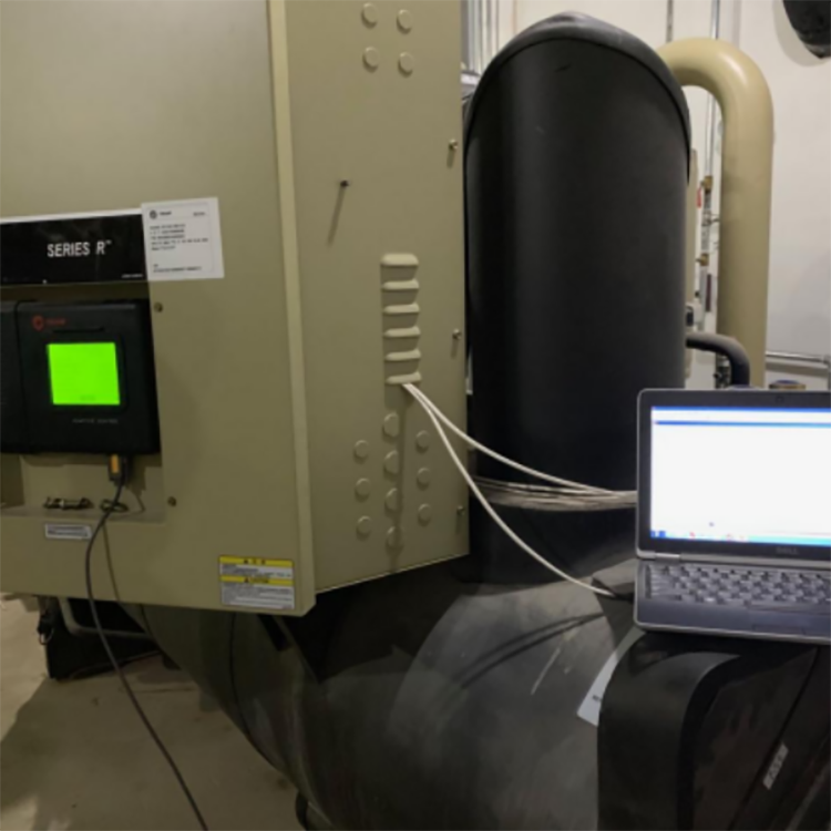
2、SCPM Compressor Protection Module3、MTA Compressor major overcurrent interruption During a field maintenance and debugging session, I found the unit alarming. Unfortunately, my memory isn't great, and I didn't remember the meaning of the alarm code. I searched online, but unfortunately, my phone is too outdated to read it.PDFFormat files onlyTXTText format reading, suddenly thought, wouldn't it be great to have an online text format query service? Hence, this post. It's convenient for general mobile internet searches; just log in to this website, find the section, and you're good to go. I hope it can be helpful in solving problems on the spot, without the need to carry a laptop or thick printed documents. From this, I hope all experts can come up with new ideas and also share their workarounds for things that don't go smoothly in their own work, slightly adjusted to improve work methods.