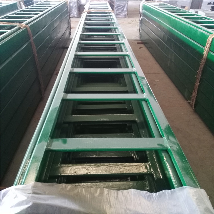


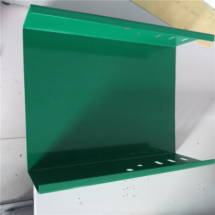
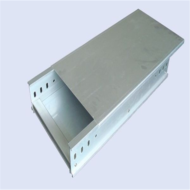
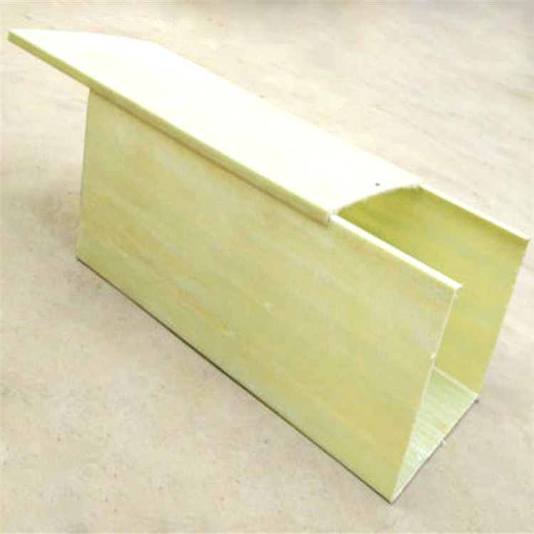


High mechanical strength, combining the rigidity of metal ladders with the toughness of fiberglass ladders, excellent corrosion resistance, strong aging resistance, attractive appearance, easy installation, and long service life. Epoxy resin and epoxy resin composite cable trays are suitable for use in environments with severe corrosion, large spans, and heavy loads.
I. Instructions for the Model Coding of Epoxy Resin Composite Cable Trays:
Epoxy resin composite cable tray model numbering is divided structurally:
1. Slot Type (C) 2. Step Type (T) 3. Pallet Type (P)
High mechanical strength, combining the rigidity of metal ladders with the flexibility of fiberglass ladders, excellent corrosion resistance, strong aging resistance, attractive appearance, easy installation, and long service life. Epoxy resin and epoxy resin composite cable trays are suitable for use in environments with severe corrosion, large spans, and heavy loads.
Description of Model Coding for Epoxy Resin Composite Cable Trays:
Section II: Selection of specifications for epoxy resin composite cable tray
The cable filling rate shall not exceed the standard规定的value. For power cables, a filling rate of 40-50% can be taken, and for control cables, a filling rate of 50-70% can be taken. Additionally, a reserve of 10-25% for engineering development should be allowed. The selection of bridgeway cross-sectional area is shown in the following table. All types of bends and accessories should meet the engineering layout requirements and be compatible with the bridgeway.
III. Selection of Load Ratings for Epoxy Resin Composite Cable Tray
Cable tray, in addition to its own weight, should also include the mechanical load it can bear for electrical wires and cables. The working uniformly distributed load should not exceed the rated uniformly distributed load of the selected load grade. When the cable tray bears the rated uniformly distributed load, its relative deflection for epoxy resin and epoxy resin composite types should not be greater than 1/200.
| Material | Span of support bracket in mm | Rated Uniform Distributed Load N/m | Deflection value | ||
| Edge height: 100mm | Edge height: 150mm | Side height: 200mm | Not applicable (mm) | ||
| Epoxy resin composite | 2000 | 1000 | 1850 | 3100 | 10 |
The strength of the load-bearing capacity of the epoxy resin composite cable tray is crucial to the reliability and durability of the structure, serving as an important basis for structural design. In actual use, besides the cable load and its own weight, the following loads should also be considered:
1. Outdoor cable trays must consider loads from wind, rain, or ice. In seismic-prone areas, inertial loads should also be taken into account.
2. Cable bridge supports should not be used as pedestrian pathways, in addition to bearing normal mechanical loads, in principle. If to be used as pedestrian pathways or for other purposes, special design for this purpose should be negotiated with the customer.
3. In the design of cable ladder load, both vertical loads and longitudinal and lateral loads during installation and use must be considered (such as the longitudinal traction force generated when laying cables and the lateral load produced when a ladder leans against the ladder).
Section 4: Configuration of support and suspension brackets for epoxy resin composite cable bridge supports.
1. Indoor support and suspension spans typically range from 1.5 to 3 meters. Outdoor pillar spans usually measure 6 meters.
2. The support and suspension configuration of non-linear sections should adhere to the following principles: When the bridge width W < 300mm, a support or suspension should be set on the straight section side, 300-600mm from the junction with the non-linear section; when the bridge width W > 300mm, in addition to meeting the above conditions, an additional support or suspension should also be added in the middle of the non-linear section.
3. When setting up multi-layer bridge racks, the center distance between layers is 200, 250, 300, and 350mm.
V. Technical Requirements for Epoxy Resin Composite Cable Trays
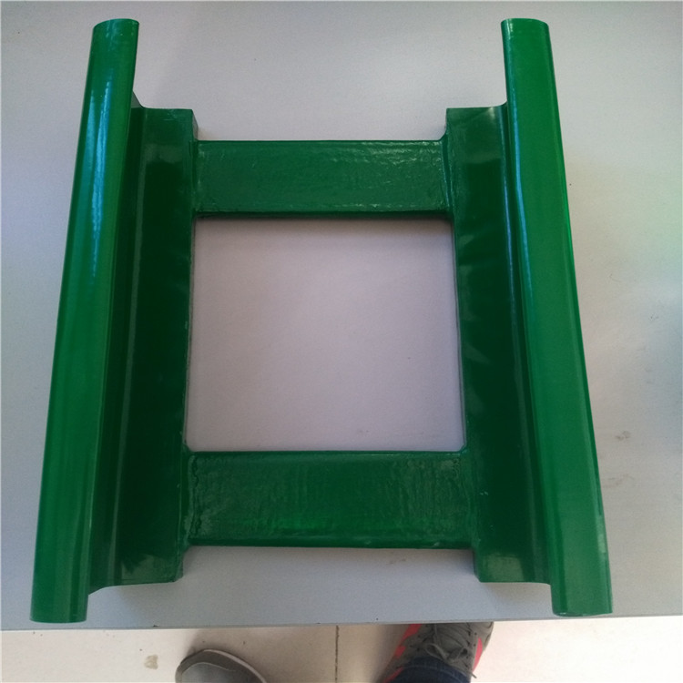
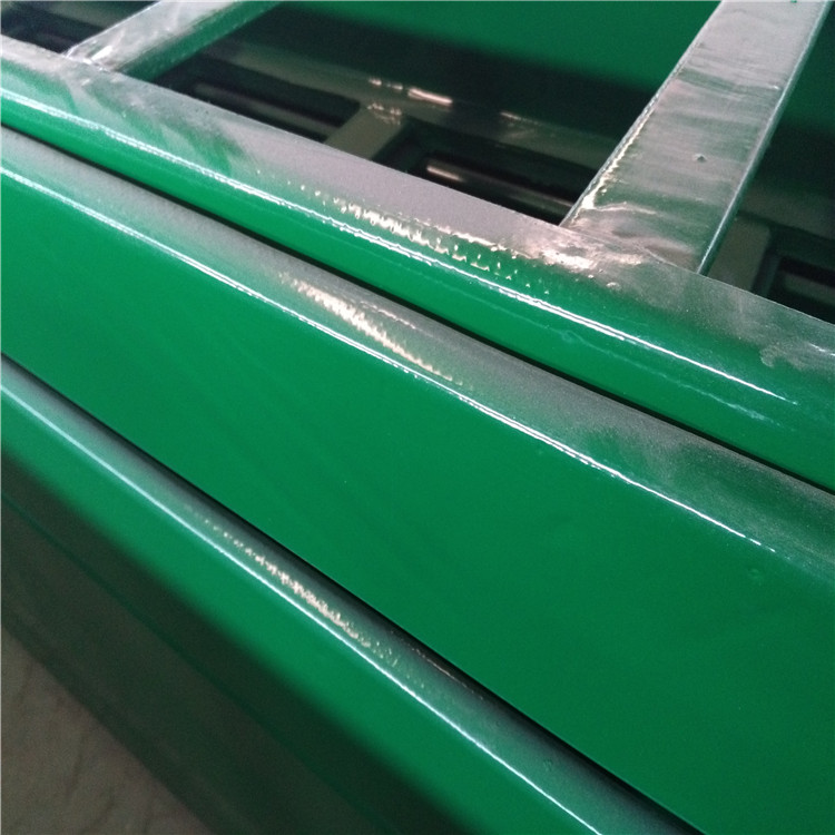
The structure is reasonably designed with aesthetic appearance, smooth surface, consistent thickness, high mechanical strength, easy installation, and corrosion and aging resistance.
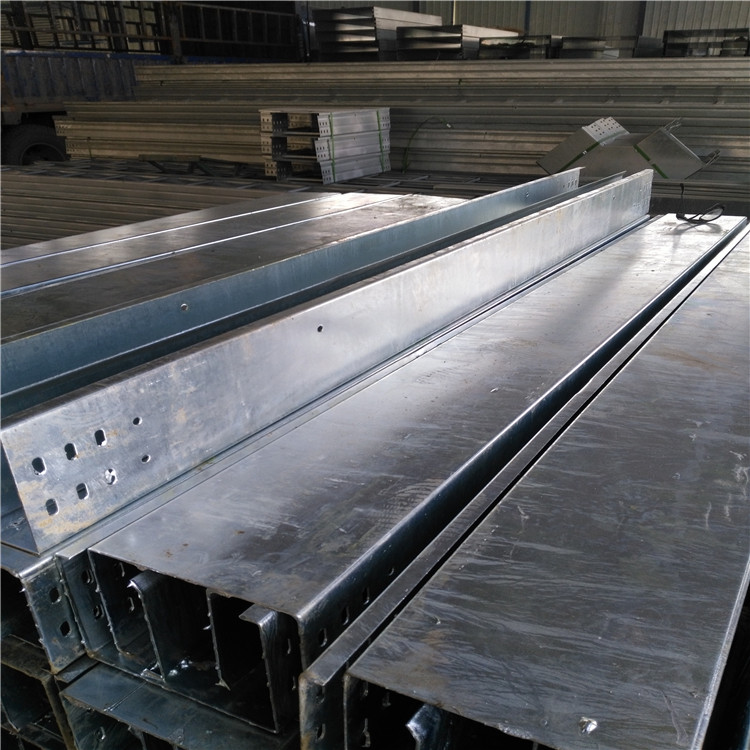
The bridge架 is made of epoxy resin composite material, lined with a metal frame, with the shape of the metal frame identical to the cross-section of the cable bridge. The material is cold-rolled steel plate, with a thickness of 1.5-2.0mm (150≤B≤300: 1.5mm, 400≤B≤800: 2.0mm). The metal surface must undergo special treatment and be coated with a soft bonding layer to prevent delamination between the metal frame and the main corrosion-resistant layer due to different thermal expansion coefficients.
The bridge tray is coated with a primary corrosion-resistant layer over the metal frame, with an average thickness of 1.5mm-2.0mm and a specific gravity of 1.7-2.0g/cm³.
The main anti-corrosion layer must be externally covered with a high-density, damage-resistant protective layer that reflects ultraviolet rays, with a smooth and aesthetically pleasing surface to enhance the aging performance and service life of the cable tray.
The lining glass fiber fabric is made from three-free (alkali-free, wax-free, and untwisted) glass fiber textiles.
The filling material is made of lightweight aluminum hydroxide to reduce its own weight, thereby enhancing the load-bearing capacity of the cable tray.
The bridge frame features measures against strong corrosion, strong external forces on any end face, connection surface, and connection holes.
The main anti-corrosion layer, bonding layer, and protective layer must be formed in one hydraulic molding process.
Corrosion-resistant, with a lifespan of up to 30 years in harsh environments such as acidic, alkaline, saline, and ammonia, without aging or fading.
Cable tray flame-retardant oxygen index is not less than 30%.
The connecting bolts are made of stainless steel bolts.