


Introduction to Hydraulic Cone Crusher
The hydraulic cone crusher is our pride, integrating advanced technology with innovative design and rational structure. Particularly, the hydraulic system achieves automated operation. It is widely used in various fields such as hydropower stations, construction materials, highways, railways, metal ore, and ceramics industries.
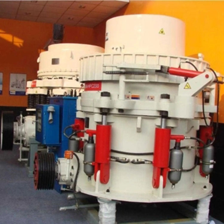
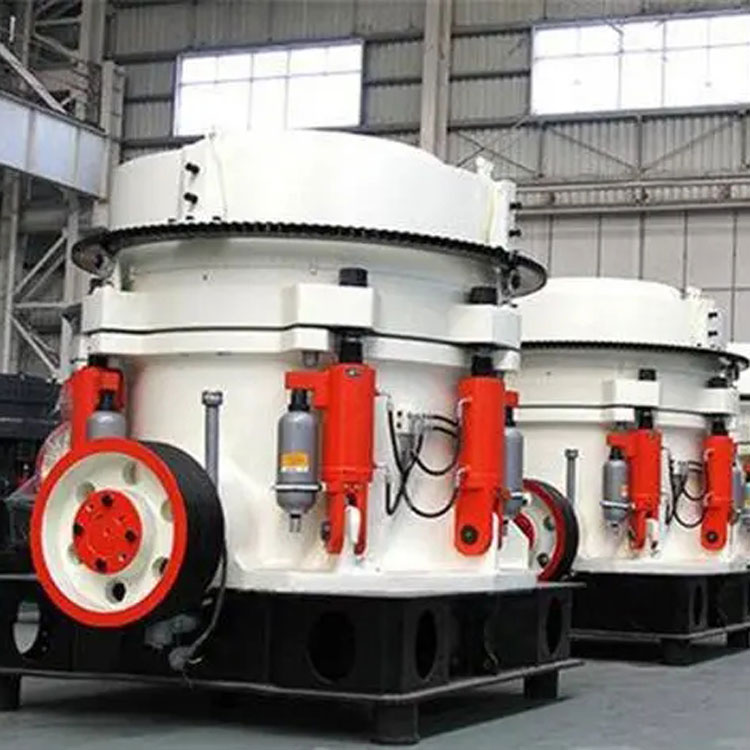
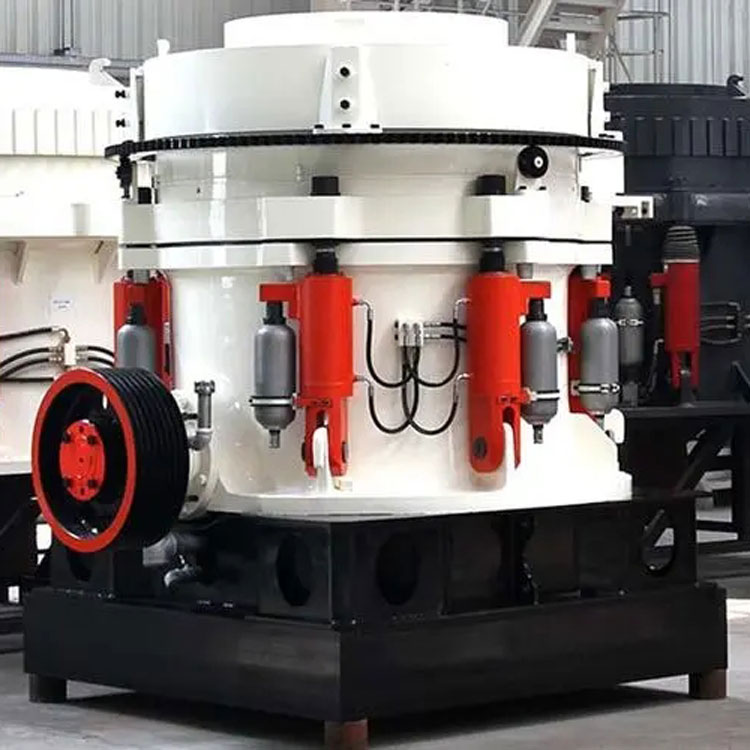
Hydraulic cone crusher structure
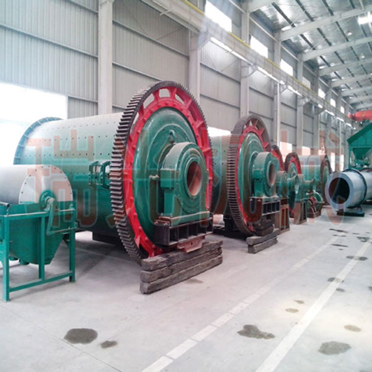
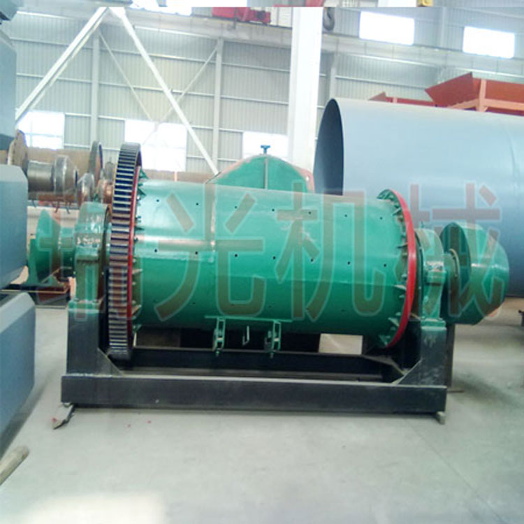
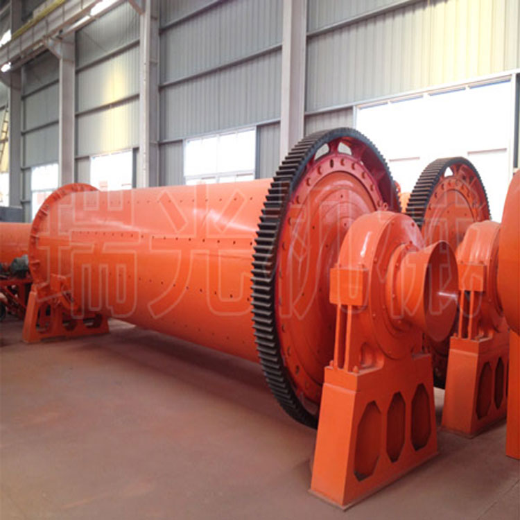
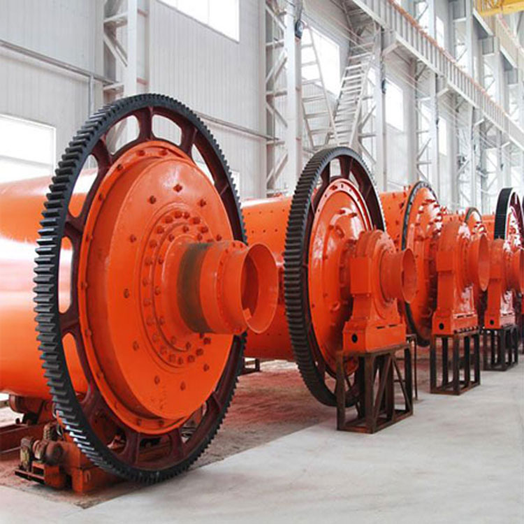
The hydraulic cone crusher (abbreviated as hydraulic cone break) is mainly composed of a motor, transmission device, movable cone, fixed cone, frame, hydraulic unit, feeding device, etc. Detailed illustrations are as follows.
Hydraulic cone crusher working principle
The hydraulic cone crusher operates by the rotation of an electric motor, which drives the cone section through a belt pulley or coupling, a drive shaft, and under the action of an eccentric sleeve, to perform a fixed-rotary motion. This causes the crushing wall of the cone crusher to alternately approach and recede from the surface of the fixed roller wall mounted on the adjusting sleeve, continuously impacting, compressing, and bending the ore within the crushing chamber, thereby achieving the破碎 of the ore.

Hydraulic cone crusher performance advantages
1. Utilizes a new layer compression crushing theory, with a crushing cavity design of a cone mill featuring layer compression crushing. The crushed material particles are mostly cuboidal, and have a small particle size.
2. The fine cone crusher revolutionizes the concept of fine crushing, increasing the discharge opening gap while ensuring appropriate compression work conditions. It utilizes a special crushing chamber to form multiple particle layers, enhancing the rock density within the crushing chamber, and fully applies the crushing energy to the rock to achieve thorough material crushing. This results in the production of more fine-grained products. Generally, the finished product content for single particle crushing is 50%, while for layered compression crushing, it is typically 70% to 80%.
3. The uniform feeding device prevents segregation of raw material particle size, ensuring stable operation and even wear on the crushing wall and the roller wall.
4. The automatic control system can continuously monitor the pressure values of the hydraulic system, the current values of the main motor, and the material level. It automatically adjusts the discharge orifice gap based on load conditions, enabling operation under high loads for increased yield and improved particle shape.
Hydraulic Cone Crusher Technical Specifications
| Model | Cavity shape | Bushing cone major diameter (mm) | Material outlet adjustment range (mm) | Recommended opening width for the smaller feed opening (mm) | Larger feeding size (mm) | Processing Capacity (t/h) | Main Motor Power (kw) | Machine Body Weight (t) |
| HXGYS 300 | C1 | 910 | 13~38 | 175 | 150 | 81~180 | 6P 90 | 10 |
| C2 | 9~22 | 102 | 85 | 60~180 | ||||
| F1 | 3~16 | 76 | 65 | 36~145 | ||||
| F2 | 3~13 | 41 | 35 | 36~130 | ||||
| HXGYS 400 | C1 | 1200 | 19~51 | 241 | 205 | 207~400 | 6P 200 | 20 |
| C2 | 16~38 | 210 | 178 | 162~350 | ||||
| C3 | 13~31 | 137 | 115 | 126~310 | ||||
| F1 | 8~25 | 105 | 89 | 109~230 | ||||
| F2 | 6~16 | 89 | 76 | 82~230 | ||||
| F3 | 3~16 | 64 | 54 | 40~230 | ||||
| HXGYS 500 | C1 | 1600 | 25~64 | 269 | 228 | 280~650 | 6P 280 | 40 |
| C2 | 22~51 | 241 | 205 | 258~450 | ||||
| C3 | 16~38 | 209 | 178 | 180~410 | ||||
| F1 | 10~25 | 133 | 113 | 162~355 | ||||
| F2 | 6~19 | 89 | 76 | 136~330 | ||||
| F3 | 5~13 | 70 | 60 | 90~300 |