


Product Introduction
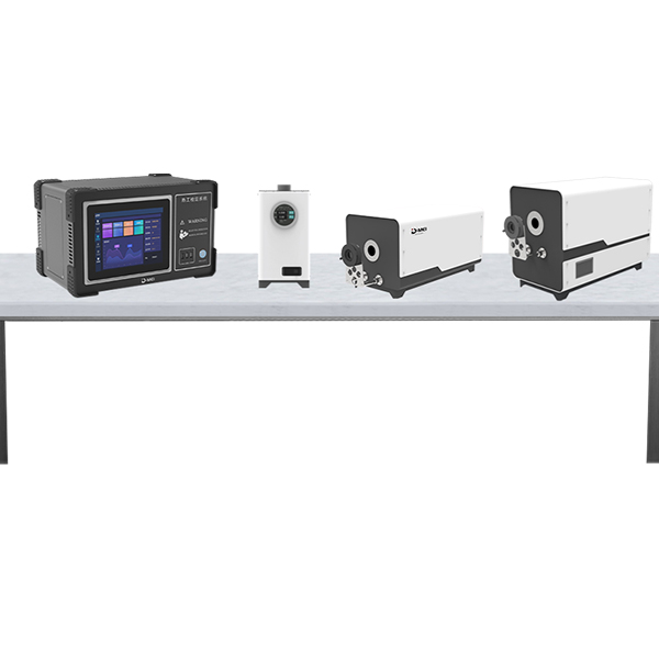
The DY-01 Type Thermocouple Automatic Testing System (300-1200℃) is an automatic testing and control system composed of a computer, printer, high-precision digital multimeter, low-voltage scanning switch, signal source (optional), and interfaces. It is a new generation of intelligent metrological standard equipment integrating computer technology, micro-electric measurement technology, and automatic testing technology. It is used for automatic calibration of various working thermocouples and high-precision signal sources, which can be calibrated in the laboratory or on-site for secondary instruments. The calibration procedures and results comply with the current national metrological calibration regulations. The system fully automates the entire thermocouple calibration process, including automatic temperature control, automatic calibration, automatic data processing, and automatic printing of calibration results. This significantly reduces the operator's workload and improves the quality of the calibration work.
Verification Scope:Multiple models of K, E, J, N, B, S, R, T type working thermocouples
The procedures required by the inspection and verification authority:The complete system meets the technical specifications stipulated by JJF1033-2008 "Regulations for Metrological Standard Assessment" and JJF1098-2003 "Regulations for Calibration of Automatic Measurement Systems for Thermocouples and Resistance Thermometers," as well as the ITS-90 International Temperature Scale.
Thermocouple calibration or verification according to regulations
JJG 141-2013 "Regulation for Calibration of Working Platinum Thermocouples"
JJG 351-1996规程 for the Verification of Working廉Metal Thermocouples
JJG668-1997 "Code of Practice for Calibration of Working Platinum/Rhodium 10-Platinum/Platinum-Rhodium 13-Platinum Short Type Thermocouples"
JJG 368-2010 "规程 for Calibration of Copper-Nickel Thermocouples Used in Work"
JJF 1262-2010 "Specification for Calibration of armored thermocouples"
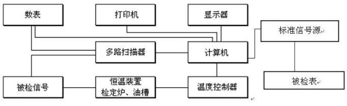
Principle of Operation for the Thermocouple Automatic Calibration Device System
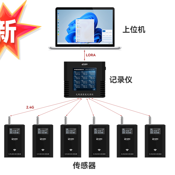
The system transmits the temperature control points to the intelligent temperature controller, which then implements temperature control for the calibration furnace. During this process, the system switches the intelligent multi-channel scanner to convert the electrical signals from the temperature sensors of the calibration furnace into digital data using a high-precision 61/2-digit digital multimeter, and transmits them to the computer via the serial communication port. The computer monitors the temperature field of the isothermal device according to relevant procedures, ensuring that the controlled object, the calibration furnace, heats up or maintains temperature as required. After reaching the specified requirements, data collection is performed by switching the smart multi-channel scanner for the tested sensor signals, generating the calibration results, and the corresponding data is entered into the database for inquiry and statistics. During the calibration process, the computer also displays various parameters in real-time. After completion of the calibration, various reports can be printed out using the printer. The computer's user-friendly operation, intelligent detection and control, and easier handling of secondary measurement instruments. The random access function for the scale and calibration procedures makes calculations and inquiries during the calibration process more convenient. The format for recording calibration data and the output format for calibration certificates can be designed according to the user's requirements, better aligning with the metrological management of the user's unit. The operation is convenient, work efficiency is high, and standards can be established. The system block diagram is as follows:
Technical Specifications
① Channel conversion switches parasitic potential ≤ 0.2μV.
② Resolution: Potential measurement resolution 0.01μV, resistance measurement resolution 0.1mΩ/0.01mΩ.
③ Accuracy: Voltage measurement accuracy ≤ 0.01%, resistance measurement accuracy ≤ 0.01%.
④ Temperature control stability: After the thermocouple calibration process is kept at a constant temperature, the furnace temperature change is ≤0.2℃/min.
⑤ Range of temperature points to be calibrated: any point between 300 to 1200°C for thermocouples.
⑥ Calibration Duration: Approximately 20 minutes per calibration point under normal conditions.
⑦ Calibration Objects: Various types of working thermocouples including K, E, J, N, B, S, R, T models.
Calibration Quantity: Up to 10 thermocouples can be calibrated simultaneously at the same temperature point, allowing for batch calibration in multiple batches.
9. Data Processing: This calibration system strictly processes data in accordance with the current national metrological calibration regulations.
. Working Conditions: Environmental Temperature: (20±3)℃, Relative Humidity: ≤75%, Power Supply: AC (220V±10%) V (50±1) Hz, Ground Resistance Requirement: ≤4Ω
Thermocouple Automatic Calibration Device Composition Description
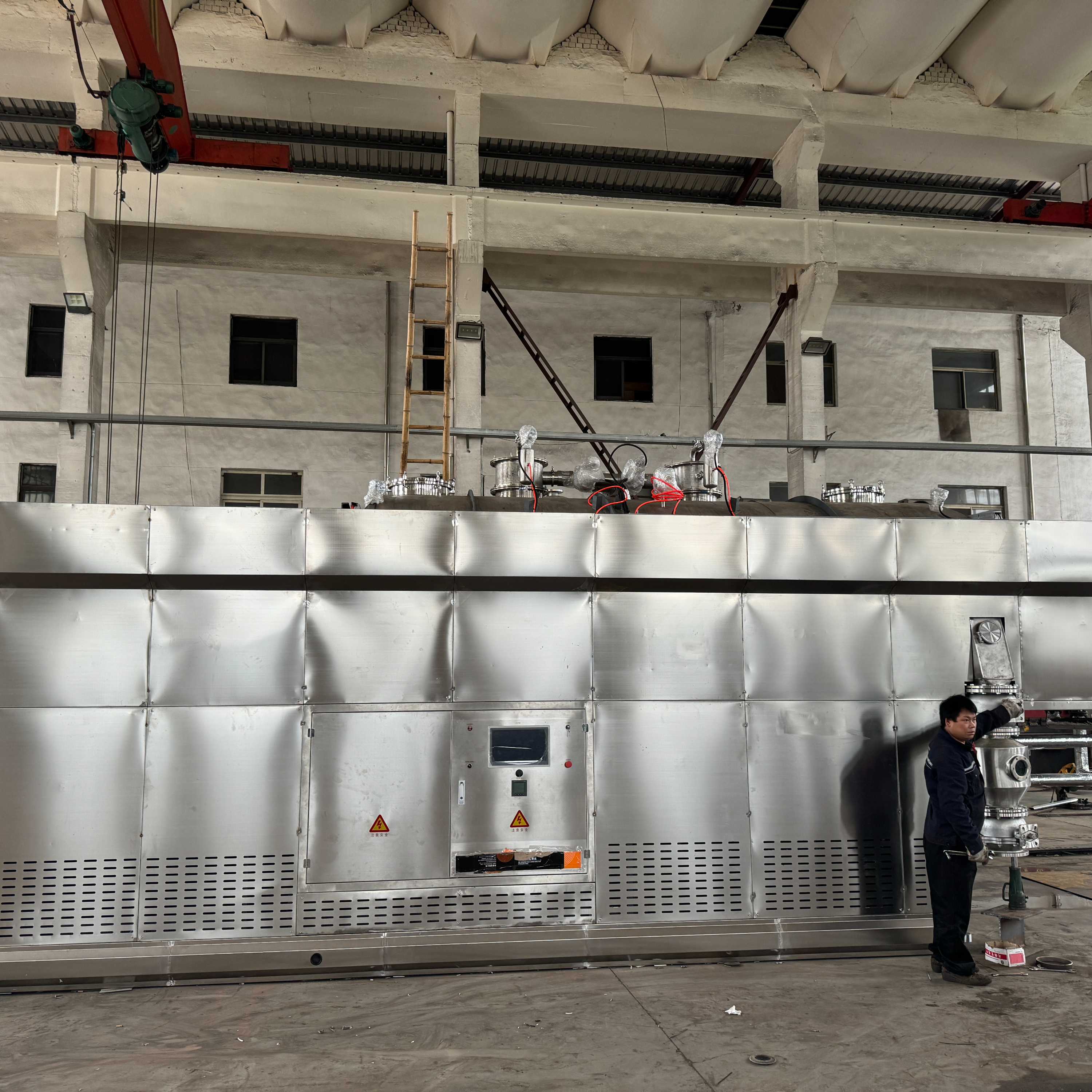
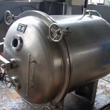
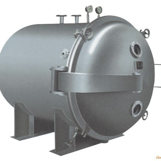
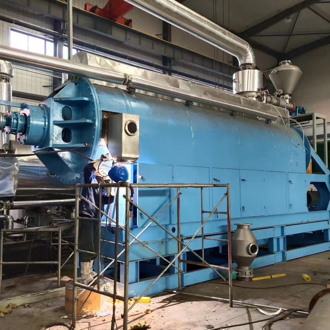
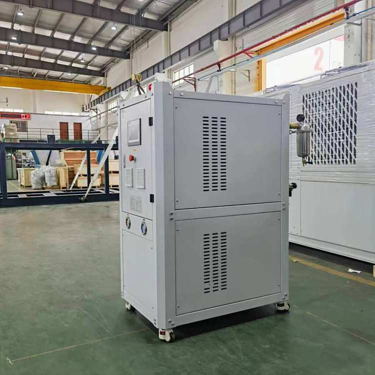
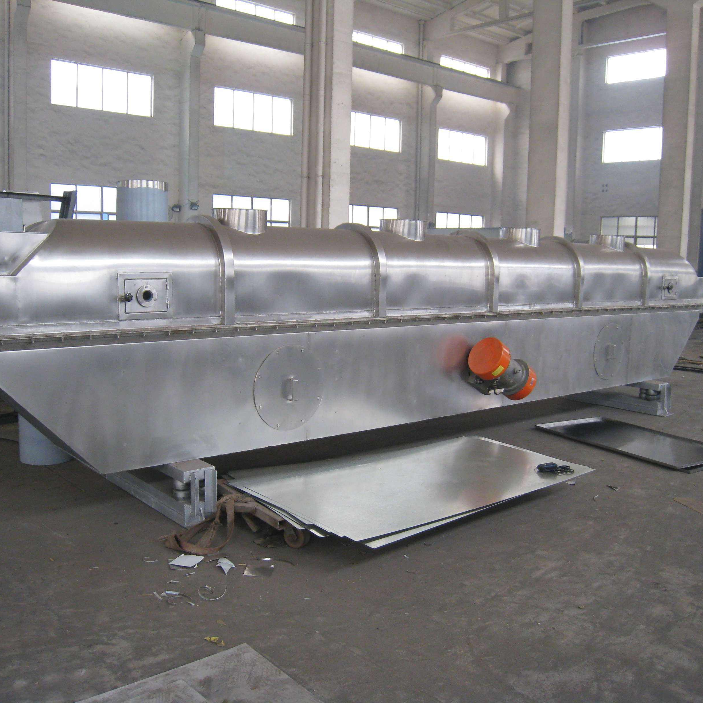
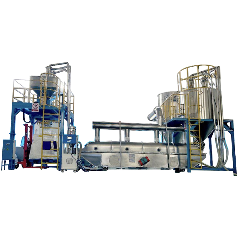
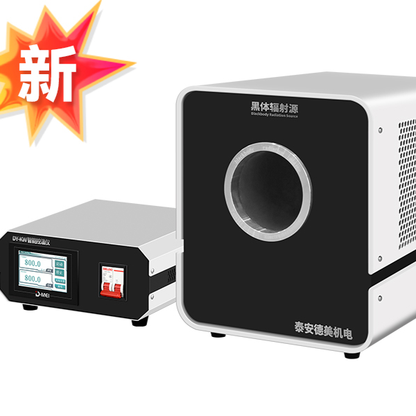
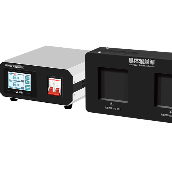
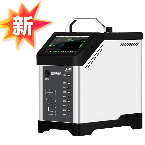
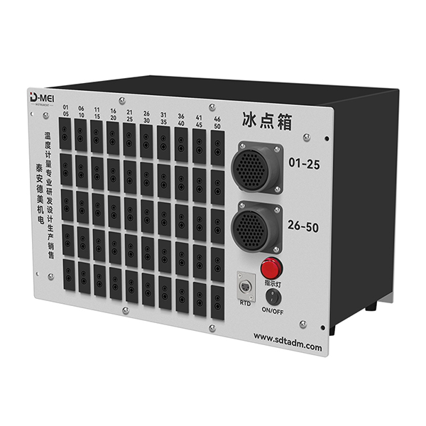
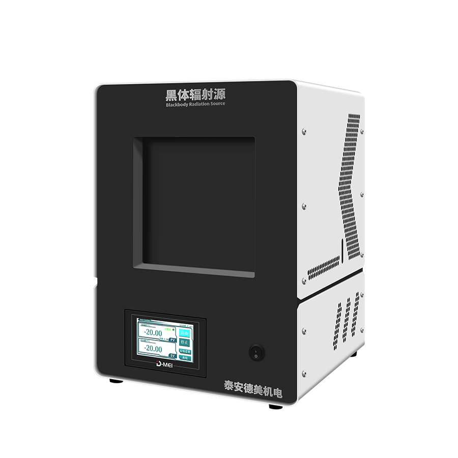
1. Constant-temperature Heat Source - A thermocouple calibration furnace (temperature range: 300℃~1200℃) or a short-type thermocouple calibration furnace (temperature range: 300℃~1200℃) is required, along with an ice point cell, to ensure good stability and uniformity of the furnace internal temperature.
2. Digital Multimeter: The digital multimeter accepts instructions from a computer, performs the required function conversions, and sends the corresponding digital signals to the microcomputer. The digital meter is a core instrument in the system that concerns the accuracy of value transmission, directly determining the reliability of the calibration data.
3. Standard Thermocouples: The thermocouple calibration program in the DY-01 thermocouple calibration system conforms to the requirements for standard thermocouples as specified in various thermocouple calibration procedures. Different standard thermocouples with different graduation numbers may be required when calibrating thermocouples with different graduation numbers. For calibration points below 300℃ of the tested thermocouples made of inexpensive metals, the calibration should be conducted in a constant-temperature bath. Additionally, a second-class standard platinum resistance should be used instead of a second-class standard thermocouple. When calibrating Class III T-type thermocouples, a second-class standard T-type thermocouple should be used as the standard below 0℃, and a second-class standard platinum resistance should be used as the standard above 0℃.
4. Software - automatic data collection, processing, and report generation. Historical records are readily accessible for review or printing at any time. The data generated by the calibration device can be automatically converted into Excel files, and information within the local network can be shared. Additionally, calibration certificates meeting various requirements can be issued.
5. Communication – The communication between various hardware within the system and with computers is achieved through direct communication technology using RS232 serial interfaces or GPIB parallel interfaces, ensuring the reliable operation of this automatic calibration system.
6. Computers - No specific hardware configuration requirements for computers; user requirements take precedence.
Key Features
The system is equipped with an imported high-precision PID intelligent temperature controller, featuring high control accuracy and a wide control range.
2. Thermocouple calibration can be set to any calibration temperature point, with the calibration point temperature set within the temperature range specified by the calibration furnace.
3. Standard couple information is inputted once based on its calibration certificate and managed through a database, allowing for the storage of multiple standard couple records simultaneously and easy retrieval upon use.
4. The heating process is monitored in real-time by a computer, with the entire temperature control process plotted as a heating curve. The screen displays detailed and comprehensive information.
5. During the calibration process, three cold-end compensation methods (zero point, room temperature compensation, and automatic tracking) are available for the user to choose from.
6. The system is specially designed with partial verification (operators can force exit by the end of the day, with the system automatically completing the subsequent verification on the next workday) and interrupted verification continuation (continuation of verification after an abnormal exit. For example: abnormal power outage, computer system failure, etc., leading to an abnormal exit of the verification system).
7. Automatically determine the grade of the inspected object based on the test data results, and print out the inspection record, inspection certificate, or inspection result notification.
8. Manage the original data after calibration in a database, allowing for retrieval and query by calibration date and the generation of reports as needed.
9. Bimetallic Thermostat Speed Lookup Manual (Lookup electric potential through temperature and temperature through electric potential)
10. Data processing of the calibration system is strictly conducted in accordance with the current national metrological calibration regulations.
11. High-precision signal sources can be calibrated both in the laboratory and on-site for secondary instruments.
12. Intelligent detection and control, making it easier to check secondary instruments.
13. Random access to the gauge table and verification procedures, making it easier for users to calculate and reference during the verification process.
14. Calibration data record formats and certification output formats can be customized to meet customer requirements, aligning more closely with the metrological management of the user's organization.