


Reasons for air knife streaks
Air knife streaks refer to streak-like defects on the steel strip as it passes through the air knife, including air knife lines, air knife stripes 8, and air knife scratches. Air knife lines, also known as air knife streaks, are caused by low pressure, low flow, or poor airflow path at a specific point on the air knife, resulting in weak zinc scraping force along a particular line on the steel strip. The coating thickness exceeds that of other areas, forming a distinct white line on the galvanized box surface. The cause of air knife stripe marks is similar to that of air knife lines, except the defect is not a single white line but a slightly wider stripe area that may not be easily noticeable. Bubbling may occur during rolling, and upon closer inspection of the galvanized sheet surface, a thicker coating can be found in a specific stripe area. Air knife scratches are continuous, patchy marks on the galvanized sheet surface caused by the steel strip rubbing against the air knife, which generally occur more frequently at the edges. The causes of air knife line streaks are mainly local damage to the air knife blade gap narrowing, zinc slag or foreign matter in the air knife lip. The solution is to clean the air knife multiple times; if the air knife line streaks are removed or their position changes, it is likely that there are zinc slag or other foreign matter in the air knife lip. If the air knife line streaks cannot be cleaned, it is necessary to check whether the air knife is damaged, and the final conclusion should be determined after the machine is stopped and the air knife is inspected. The cause of air knife stripe marks is largely due to zinc slag or zinc crystals at the tip and top surface of the air knife lip, causing the airflow path to deviate and affecting the zinc scraping force, so slightly wider streaks are affected. Air knife scratches often occur when the steel strip rubs against the air knife due to poor sheet shape, too small air knife gap, insufficient steel strip moisture, poor air knife position, or poor stability roller performance. Since it is a physical scratch, the cause is relatively simple and easy to handle, but attention must be paid to the entire stability roller issue.
Occasionally, after hot-dip galvanized roller finishing, the roller surface may exhibit a series of scratch-like marks, appearing densely across the entire surface in concentric circles, affecting both working and supporting rollers. These marks can appear within a couple of days to several days, depending on usage frequency. Upon closer examination of the roller surface, as shown in Figure 2-35, it can be observed that these defects are not indentations into the roller surface but rather adherent zinc slag particles on the working roller surface, while the supporting roller surface shows indented defects but not scratches. If both the working and supporting rollers of the finishing machine are newly ground, zinc slag particles first adhere to the working roller surface, and under high pressure, the adhered zinc slag prints on the working roller surface cause the supporting roller surface to develop corresponding indented marks, which are less severe. This process typically takes 7 to 10 days. If only the working roller is replaced without changing the supporting roller, defects on the working roller will appear quickly, within just a couple of days. Why do zinc slag particles adhere in such a regular, linear pattern on the roller surface, forming complete circles that resemble scratches? This is mainly due to a "linear adhesion effect." When there is relative motion between the roller and the steel strip, oils, iron shavings, and zinc slag particles on the steel strip adhere to the roller in a linear pattern, eventually forming complete lines of adhesion. In situations with sliding friction, it's impossible for large areas of the aforementioned impurities on the steel strip to adhere to the steel plate, as the adhesion process not only involves adhesion but also sliding friction that can cause the adhered impurities to fall off. However, there is a characteristic to this effect: if there is a dense adhesion of impurities on the roller surface that cannot be easily removed, not only will these impurities not fall off, but also impurities located at positions downstream in the direction of motion. This is because the existing adhesions have withstood the frictional force of adhesion, making it easy for them to also adhere to impurities. Moreover, the impurities at these two points protect each other. This continuous development leads to the formation of a series of continuous lines of adhered impurities on the roller surface. The surface of hot-dip galvanized sheets inevitably contains a large amount of zinc slag, which can be compressed into powder under the high pressure of roller finishing. Under the "linear adhesion effect," this powder adheres to the roller surface in circular patterns. Similarly, oil on the surface of pre-treatment steel strips will adhere to the squeezing roller in circular patterns, and iron shavings on the surface of steel strips in the furnace will adhere to the bottom roller in circular patterns of oxidized slag lines. Several conditions lead to this phenomenon in roller finishing: 1) the presence of brittle zinc slag; 2) sliding between the roller and steel strip, which occurs to some extent due to speed differences between the roller and steel strip, except for the larger tension rollers with a larger contact angle, where sliding is minimal; 3) the low hardness of the roller surface, which facilitates the adhesion of zinc slag. If coated with a chrome layer, this phenomenon is largely avoided. Measures to prevent this defect include: 1) using high-pressure water spray to rinse the surface of the working roller, washing off the adhered zinc slag; 2) using chrome-plated rollers to increase the roller surface hardness. By implementing these measures, the defect of roller finishing marks can generally be eliminated.
Precautions for using color coated coils
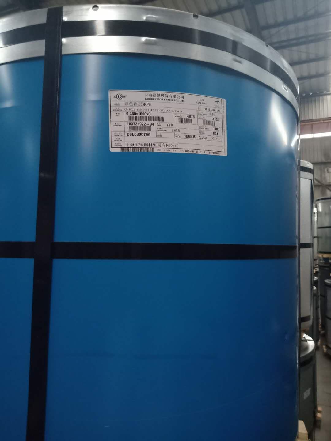
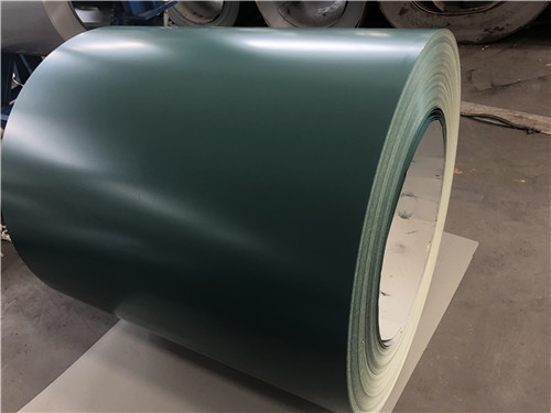
Color-coated coils are lightweight, aesthetically pleasing, and have excellent corrosion resistance, making them easily processable. Colors typically include gray-white, sea blue, and brick red, and they are mainly used in the advertising, construction, home appliance, electrical, furniture, and transportation industries. What should be noted during use? Here's a brief introduction:
When using color coated coil on a building, it is necessary to use products from the same factory, same production line, and same batch to avoid mixing.
(2) Membrane application is necessary during forming for materials like PVDF-coated color coated coils and aluminum-zinc plated sheets.
(3) When shearing colored coated coils, the equipment's surface in contact with the colored coated coils should be covered with a rubber mat.
(4) Promptly remove metal shavings from cutting to prevent scratching the coating on the color coated board.
(5) Zinc can act as a sacrificial anode to protect steel, but it's recommended to place the cut edges of the coated steel coils in concealed areas during use. For projects with stringent requirements, the cut edges must be protected.
(6) Upon completion of the engineering installation, it is essential to promptly remove weld points and metal shavings left from construction from the coil to prevent corrosion of the color steel panels.
That concludes the precautions to take when using color-coated coils. Proper usage is key to maximizing the value of color-coated coils, and we hope this information aids you in your use of these products.
Reasons for surface pressure spots on color coated coil
Color-coated coil is very popular now, but why do pressure spots appear during the production process? Let's learn about the specific reasons below:
Compared to construction-grade boards, the base material used in electrical appliances' color-coated coils has a higher elongation yield ratio and corresponding r and n values. It also requires a strong adhesion between the paint film and the base material, with the coating having certain flexibility and lower hardness. During the shearing and unwinding of color-coated steel coils for appliances, surface defects such as surface pressure spots often occur. This defect is caused by slight deformation of the coating surface during rolling after baking and cooling due to the rolling tension, sometimes resulting in a rough surface and visible pressure spot patterns. Minor pressure spot defects will gradually disappear over time as the steel plate is stored, and can also be eliminated by heating. However, more severe pressure spot defects cannot be removed even with the aforementioned measures, thereby affecting the user experience.
Streaks are defects that arise during the production process. To identify the causes and influencing factors of such defects during production requires multiple shutdowns for troubleshooting, which affects production schedules and increases costs. Therefore, it is necessary to simulate and replicate this defect in a laboratory, evaluate it, and seek out the causes of the defect and factors influencing it from all aspects.
That's the reason for the pressure spots on color-coated coils. We believe you now have a deeper understanding of the surface pressure spots on color-coated coils. We hope the above information helps you avoid surface pressure spots during production.
The air knife is a more precise piece of equipment among hot-dip galvanized wire, with high requirements for its shape, position, and precision, not just in terms of manufacturing quality, but also during daily adjustments.
(1) The impact of the upper and lower lips alignment on the air knife
If the upper and lower lips of the air knife are aligned front to back at the same horizontal plane, the emitted airflow is consistent with the air knife gap, resulting in a stable thickness of the airflow blown out, which is easier to control in actual production. This is beneficial for producing zinc-coated products with stable surface quality. If the upper knife lip is forward and the lower knife lip is behind, the airflow scattered downward after passing through the air knife forms longitudinal divisions upon contact with the zinc-coated steel strip. Since most of the airflow is downward, it is advantageous for improving the flow direction of zinc on the steel strip's surface. However, at a lower air knife height, it is prone to zinc splashes, causing clogs or nodules in the air knife nozzle. Additionally, the increased thickness of the scattered airflow makes it difficult to control the zinc flow patterns on the zinc-coated steel strip's surface and the air knife's transverse patterns, which is不利 for producing zinc-coated products with high surface quality. If the lower knife lip is forward and the upper knife lip is behind, the airflow scattered along the steel strip's running direction causes zinc to fly up after being jetted by the air knife. The zinc splashes form dross that contacts the steel strip's surface, easily leading to surface quality defects. Moreover, the zinc splashes are prone to causing clogs or nodules in the air knife's transverse direction. Therefore, when manually adjusting the position of the air knife lips, strict control of adjustment accuracy is essential to avoid the situation where the lower knife lip is forward and the upper knife lip is behind.
Steel strips exhibit adhesion slagging upon exiting the zinc pot, primarily occurring at the strip edges, with two types of defects: edge feathering and edge slag particles. Edge feathering happens when the production line speed is slow and the galvanized layer is thick, resulting in lower air knife pressure. This is mainly due to the edge effect on the steel strip under the air knife's action, which is amplified when the air knife pressure is low. If the speed and flow rate of the gas emitted from the air knife are uniform, the impact pressure on the center of the steel strip is also uniform. However, at the edges, there is a significant effect, with part of the airflow deflecting outward towards the strip edge, reducing the impact force. Simulation calculations using the specialized computational fluid dynamics software Fluent also confirm this. The principle of edge feathering slagging is shown in Figure 2-33. Edge slag particle defects often occur during the hot galvanizing process for thick plates, especially when the edges are cut or the strip edges form a serrated shape, leading to the same edge effect. In this case, the slagging is not on the surface of the steel plate but on the side, with the slag mainly consisting of granular bottom and top slag. The side of thick plates is wider, and if there are burrs or edge cracks after shearing, it provides conditions for the adhesion of zinc slag particles. When the steel strip or steel plate defects adhere to the zinc liquid and new zinc slag is formed, it cannot be blown off by the air knife due to the lower edge pressure, leaving it at the edge of the galvanized coating, causing edge zinc slag defects. The best way to address these two defects is to use edge baffles to overcome the edge effect and adjust the air knife angle to -2" to 4", with a difference of 1" to 2" front and back. This enhances the zinc scraping force of the airflow and can also lower the air knife height to shift the low-pressure region at the steel strip edge, thereby improving quality.
Analysis of Air Knife Defects
The air knife mark is a linear protrusion that occurs when the steel strip passes through the air knife after being electroplated, characterized by its continuous and outward bulging nature. The zinc coating at the air knife mark is thicker, thus causing the linear protrusion. To determine if it is an air knife mark, the protruding streak should be washed away with hydrochloric acid, and the steel plate surface should appear normal without any pre-coating scratches. If there are pre-coating scratches, it is not an air knife mark.
The fundamental cause of slag adhesion defects is to reduce the amount of zinc slag produced, with common measures mainly involving the following aspects:
① Utilizing cold-rolled steel sheets with minimal surface oil and iron powder, typically requiring the oil and iron filings on the surface of the cold-rolled sheet material to be less than 400mg/m2, or with a reflectivity greater than 50%.
② Strictly control the pretreatment quality to minimize oil and iron powder residues post-pretreatment—generally less than 50~80mg/m².
Avoid oxidation of the steel strip during rolling, storage and transportation, as well as inside the annealing furnace.
④Strictly control the temperature of zinc and copper, generally requiring 460℃+1℃, not exceeding 470℃, and strictly prohibiting exceeding 480℃. Keep the temperature fluctuation of the zinc pot within ±1℃. Strictly control the temperature of the steel strip entering the zinc pot. Steel plates thicker than 1.2mm are not allowed to exceed 4℃ of the zinc pot temperature. Medium plates ranging from 0.8 to 1.2mm are not allowed to exceed 10℃ of the zinc pot. Thin plates from 0.4 to 0.8mm are not allowed to exceed 15℃ of the zinc pot. Ultra-thin plates from 0.2 to 0.4mm are not allowed to exceed 30℃ of the zinc pot.
⑥ Maintain the aluminum content in zinc pots between 0.16% to 0.20%. Low content can cause intense iron-zinc reactions and increase zinc slag; high content reduces iron solubility in zinc, promoting slag precipitation. ⑦ Prevent iron sheets, oxide scales, and other impurities from falling into the zinc pot. If they do, they must be cleaned up immediately.
③ Employ bottom slag-free operation process to prevent the generation of bottom slag. For galvanized iron pot wire, frequently remove the bottom slag to prevent it from floating up.
For the production of color coated base sheets, consider reverse coiling or reverse uncoiling to minimize impact.
After-coating scratches refer to the scratches that occur on galvanized steel strips after the zinc coating process, specifically scratches on the zinc coating surface from the cooling tower to the coiling section, which are concave into the zinc-coated sheet surface, and the zinc metal can be seen under light. Possible situations that may cause scratches on the zinc coating surface on the galvanizing line include: (1) The steel strip deviates from the production line, rubbing against structural steelwork, etc., causing surface abrasions. (2) Zinc slag and debris adhere to the surface of the idler roller, causing scratches on the steel strip surface when the roller operates poorly. Such rollers may include: the cooling tower top reversing roller, other reversing rollers, correction rollers at various locations, tension measurement rollers, post-processing extrusion rollers or passivation coating rollers, fingerprint-resistant coating rollers, live-lug reversing rollers, and idlers at various locations. (3) The steel strip, due to vibration in the small zinc flower equipment area, rubs against the small zinc flower equipment, causing localized scratches. (@) When the steel strip runs between the cooling air boxes, due to the effect of the cooling air flow, it may flutter and rub against the surface of the cooling air box, causing abrasions. (5) The steel strip slips on the water quenching tank roller, and if there is scale on the surface of the water quenching tank roller, it is prone to cause many dense scratches on the steel strip surface. Therefore, the water quenching tank roller should be treated with rubber to increase friction, and the water for the water quenching tank must be desalinated water to remove calcium and magnesium ions from the water, preventing scaling on the roller surface in warm water. (6) Zinc slag and impurities fall on the tension roller assembly, causing scratches when the steel strip passes through. 0 The nozzle of the spray-type passivation treatment system is loose, scratching the steel strip; or the material tray of the roller coating passivation system is too close to the steel strip, causing abrasions. 3 The drying system for fingerprint-resistant coating is too close to the steel strip, causing localized abrasions when the steel strip vibrates due to low tension. 0 The exit cutting shear is too close to the steel strip, causing localized abrasions when the steel strip is loose. 0 There are foreign objects on the exit feeding platform, and the steel strip is scratched when sliding on its surface. It is relatively easy to locate and address these issues, as early detection will not cause significant impact.
WeChat Official Account

Scan to follow Official Account


