


Overview
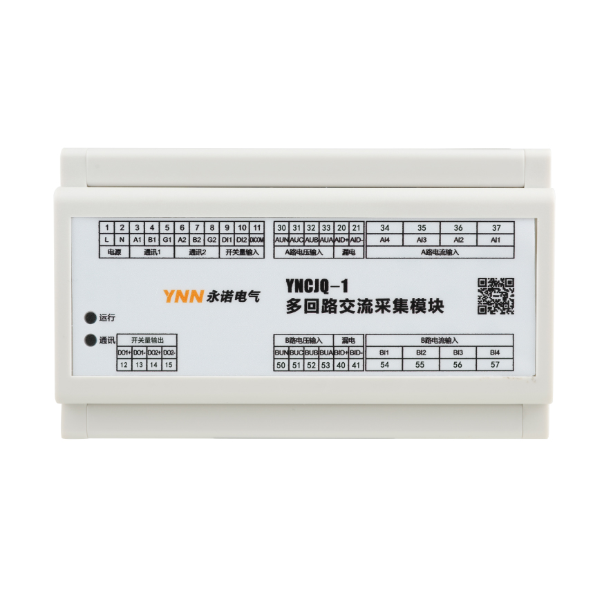
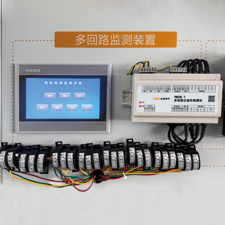
The Multi-loop AC Acquisition Module is a multi-loop measuring instrument (hereinafter referred to as the instrument) with programmable measurement and digital communication functions, capable of completing AC single-phase 24-loop electricity measurement, energy metering, data collection, and transmission. It is widely applicable in data centers, power distribution automation, intelligent buildings, and internal electricity measurement, management, and assessment within enterprises. It features two RS485 digital communication interfaces, which, when paired with our company's xxx touch screen, enable local data visualization. Additionally, the second RS485 interface can be connected to a data collection center for remote data statistics.
Additionally, the sampling loop employs an isolation design, with 12 circuits on each of the A and B sides, and can also be used for dual-power systems.
Technical Specifications
| Performance | Parameters | ||
| Input measurement display | Internet | Three-phase four-wire or single-phase | |
| Voltage | Rated Value | AC 500V | |
| Overload | Ongoing: 1.2 times (continuous) / 2 times rated value within 1 second | ||
| Power Consumption | <0.4VA (per phase) | ||
| Impedance | >2MΩ | ||
| Accuracy | RMS measurement, accuracy grade 0.5 | ||
| Current | Rated Value | AC 5A or AC 100A (External integrated transformer, 2000/1 ratio, crystal head output) | |
| Overload | Continuously: 1.2x Instantly: 10x/1s | ||
| Power Consumption | <0.2VA (per phase) | ||
| Impedance | <2mΩ | ||
| Accuracy | RMS measurement, accuracy grade 0.5 | ||
| Frequency | 45~65Hz | ||
| Power | Apparent Power, Active Power Accuracy: 1.0 Class, Reactive Power Accuracy: 2.0 Class | ||
| Electric Power | Four-quadrant measurement, active accuracy of 1.0 class, reactive accuracy of 2.0 class | ||
| Power Supply | Scope of Work | AC 85~270V or DC 100~350V | |
| Power Consumption | ≤3VA | ||
| Output | Digital Communication | RS-485, MODBUS RTU Protocol | |
| Environmental | Work environment | -10~55℃ | |
| Storage Environment | -20~75℃ | ||
| Safety | Pressure-resistant | See voltage withstand specifications | |
| Insulation | Input, output, power to housing > 50MΩ | ||
| Enhanced features | Switched quantity input | 2 | |
| Switched quantity output | 2 | ||
| Leakage Current Measurement | 2 | ||
| Installation Method | Guide rail installation | Standard 35mm rail mounting | |
Dimensions and Installation
Dimensional drawing

Installation Diagram

Function Description
Measurement
Measure voltage, current, active power, reactive power, apparent power, power factor, and frequency parameters for each loop. Read via RS485 communication. After setting the correct ratio, the values read are the primary values.
Measurement
Measure parameters for forward active energy, reverse active energy, forward reactive energy, and reverse reactive energy; read via RS485 communication. After setting the correct ratio, the value read is the primary value.
Leakage Current
Equipped with two-way leakage current measurement function, suitable for external use with a 1A leakage current transformer.
Switched Quantitative Input
The input module utilizes a dry contact resistor switch signal input method, featuring an internal power supply within the instrument, eliminating the need for external power. It is suitable for monitoring nodes such as fault alarms, switch positions, handcart locations, and capacitor compensation cabinet capacitor input states. Status information can be remotely transmitted to the intelligent monitoring system via communication interfaces.
Relay Output
Equipped with dual relay output function, relay capacity: AC250V/5A, DC30V/5A. Relays operate in remote control mode, with the meter connected to the backend system via communication interface. The backend system can control relay switching and output pulse signals.
RS485 Communication Function
Equipped with dual RS485 communication capability, baud rates are selectable from 1200 to 38400 bps, supporting odd, even, and no parity checking, and utilizing the Modbus-RTU communication protocol.
Voltage, Current Ratio
Adjustable voltage and current ratios for intuitive parameter reading by the backend system.
In conditions where the current is 100A or less, a 100A/0.05A current transformer is used, with the current ratio set to 1.
When the current exceeds 100A, transformer cascade is required. For instance, with a primary current of 200A, a 200A/5A current transformer must be used first, followed by a 5A/2.5mA transformer connected to the meter, with the current ratio set to 40 (200/5).