


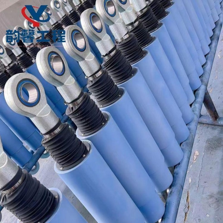
Viscous Damper (VFD)
Viscous dampers, as part of the structural protection system, provide a reverse viscous damping force during the relative movement of the structure. The damping force of the viscous dampers originates from the internal interactions within the structure, including:
① The interaction between the damping medium and the piston.
② The interaction between the damping medium and the oil cylinder;
③Interaction between media.
④ Interaction between the piston rod and the sealing parts.
This force, acting in the opposite direction to the piston's movement speed, is known as the damping force. During the operation of the damper, these interaction processes convert mechanical energy into thermal energy and dissipate it.
Hengshui Yunxin Engineering Design Co., Ltd. is committed to the technological development of the third-generation viscoelastic fluid damper. Based on understanding and mastering the domestic and international product technology developments, we have developed a new generation of viscoelastic fluid damper products, considering both process and heat dissipation. We have also applied for national patents.
2. The third-generation viscous fluid damper can be defined as:
① Utilizes low-viscosity methyl silicone oil as the medium.
② The hysteresis curve is full, and the energy consumption mechanism meets the nonlinear N-S equation.
③ High-efficiency, long-life sealing system
④ Low-speed friction damping is low, less than 10% of the rated load.
Product has a long lifespan, no oil leakage, stable performance, reusable, with both shock resistance and wind resistance.
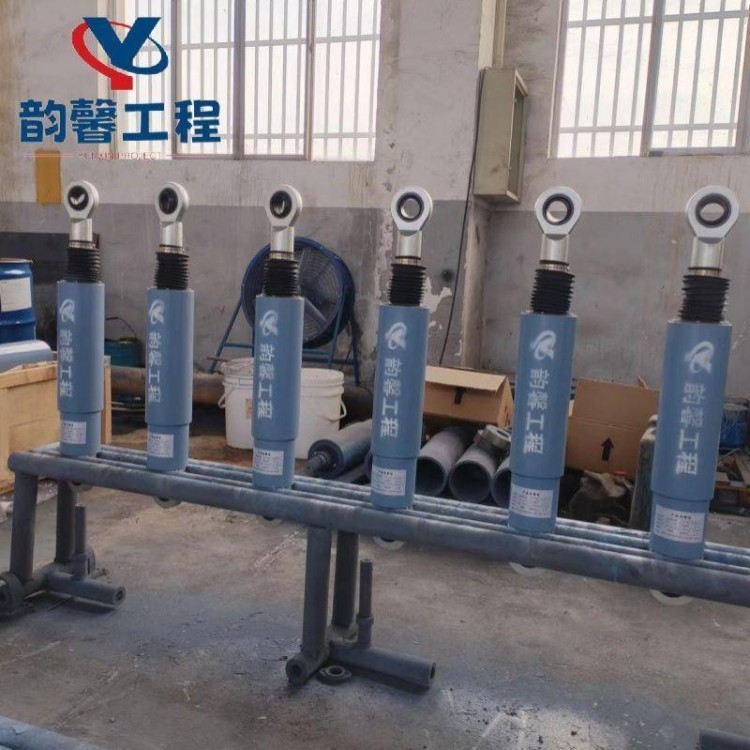
3. Damper shape and geometric dimensions:
![]()

Table 1: Damper外形Parameters:
Serial Number | Rated Load (kN) | Shaft diameter d (mm) | Outer Diameter D (mm) | Travel Distance S (mm) | Sales Distance L (mm) |
1 | 30 | 20 | 60 | ±600 | Based on customer installation requirements, custom design |
2 | 60 | 25 | 83 | ||
3 | 100 | 35 | 102 | ||
4 | 160 | 40 | 127 | ||
5 | 250 | 50 | 152 | ||
6 | 400 | 60 | 194 | ||
7 | 650 | 80 | 245 | ||
8 | 1000 | 100 | 325 | ||
9 | 1800 | 140 | 402 | ||
10 | 2400 | 160 | 450 | ||
11 | 3000 | 180 | 500 | ||
12 | 3500 | 200 | 554 | ||
13 | 4000 | 220 | 610 |
4. Selection Parameters
F=CVα
In the formula: F is the maximum damping force, C is the damping coefficient, V is the design speed, and α is the speed exponent.
Rated Load (kN) | C damping coefficient (kN·(s/mm)α) | Speed Index | V-design speed (mm/s) | Note |
200 | 70 | 0.15 | 1000 | Seismic-resistant |
200 | 85 | 0.15 | 300 | Seismic-resistant |
200 | 100 | 0.15 | 100 | Seismic-resistant |
200 | 50 | 0.2 | 1000 | Seismic-resistant |
200 | 65 | 0.2 | 300 | Seismic-resistant |
200 | 80 | 0.2 | 100 | Anti-seismic |
200 | 25 | 0.3 | 1000 | Seismic-resistant |
200 | 35 | 0.3 | 300 | Seismic-resistant |
200 | 50 | 0.3 | 100 | Seismic-resistant |
200 | 6 | 0.5 | 1000 | Seismic-resistant, wind-resistant, bridge |
500 | 125 | 0.2 | 1000 | Seismic-resistant |
500 | 160 | 0.2 | 300 | Seismic-resistant |
500 | 200 | 0.2 | 100 | Seismic-resistant |
500 | 65 | 0.3 | 1000 | Seismic-resistant |
500 | 90 | 0.3 | 300 | Seismic-resistant |
500 | 125 | 0.3 | 100 | Seismic-resistant |
500 | 32 | 0.4 | 1000 | Seismic-resistant, wind-resistant, bridge |
500 | 51 | 0.4 | 300 | Seismic-resistant, wind-resistant, bridge |
500 | 80 | 0.4 | 100 | Seismic-resistant, wind-resistant, bridge |
500 | 0.5 | 1 | 1000 | Seismic-resistant, wind-resistant, bridge |
800 | 200 | 0.2 | 1000 | Seismic-resistant |
800 | 255 | 0.2 | 300 | Seismic-resistant |
800 | 320 | 0.2 | 100 | Seismic-resistant |
800 | 100 | 0.3 | 1000 | Seismic-resistant |
800 | 145 | 0.3 | 300 | Seismic-resistant |
800 | 200 | 0.3 | 100 | Seismic-resistant |
800 | 0.8 | 1 | 1000 | Seismic-resistant, wind-resistant, bridge |
1000 | 250 | 0.2 | 1000 | Seismic-resistant |
1000 | 320 | 0.2 | 300 | Seismic-resistant |
1000 | 400 | 0.2 | 100 | Seismic-resistant |
1000 | 125 | 0.3 | 1000 | Seismic-resistant |
1000 | 180 | 0.3 | 300 | Seismic-resistant |
1000 | 250 | 0.3 | 100 | Seismic-resistant |
1000 | 63 | 0.4 | 1000 | Seismic-resistant, wind-resistant, bridge |
1000 | 100 | 0.4 | 300 | Seismic-resistant, wind-resistant, bridge |
1000 | 160 | 0.4 | 100 | Seismic-resistant, wind-resistant, bridge |
1500 | 190 | 0.3 | 1000 | Seismic-resistant |
1500 | 270 | 0.3 | 300 | Seismic-resistant |
1500 | 375 | 0.3 | 100 | Seismic-resistant |
1500 | 47 | 0.5 | 1000 | Seismic-resistant, wind-resistant, bridge |
1500 | 87 | 0.5 | 300 | Seismic-resistant, wind-resistant, bridge |
1500 | 150 | 0.5 | 100 | Seismic-resistant, wind-resistant, bridge |
1500 | 1.5 | 1 | 1000 | Seismic-resistant, wind-resistant, bridge |
2000 | 250 | 0.3 | 1000 | Seismic-resistant |
2000 | 360 | 0.3 | 300 | Seismic-resistant |
2000 | 500 | 0.3 | 100 | Seismic-resistant |
2000 | 127 | 0.4 | 1000 | Seismic-resistant, wind-resistant, bridge |
2000 | 205 | 0.4 | 300 | Seismic-resistant, wind-resistant, bridge |
2000 | 315 | 0.4 | 100 | Seismic-resistant, wind-resistant, bridge |
2000 | 63 | 0.5 | 1000 | Seismic-resistant, wind-resistant, bridge |
2000 | 2 | 1 | 1000 | Seismic-resistant, wind-resistant, bridge |
2500 | 315 | 0.3 | 1000 | Anti-seismic |
2500 | 450 | 0.3 | 300 | Seismic-resistant |
2500 | 630 | 0.3 | 100 | Seismic-resistant |
2500 | 160 | 0.4 | 1000 | Seismic-resistant, wind-resistant, bridge |
2500 | 255 | 0.4 | 300 | Seismic-resistant, wind-resistant, bridge |
2500 | 396 | 0.4 | 100 | Seismic-resistant, wind-resistant, bridge |
2500 | 80 | 0.5 | 1000 | Seismic-resistant, wind-resistant, bridge |
2500 | 145 | 0.5 | 300 | Seismic-resistant, wind-resistant, bridge |
2500 | 250 | 0.5 | 100 | Seismic-resistant, wind-resistant, bridge |
2500 | 2.5 | 1 | 1000 | Seismic-resistant, wind-resistant, bridge |
3000 | 750 | 0.2 | 1000 | Seismic-resistant |
3000 | 960 | 0.2 | 300 | Seismic-resistant |
3000 | 1200 | 0.2 | 100 | Seismic-resistant |
3000 | 380 | 0.3 | 1000 | Seismic-resistant |
3000 | 540 | 0.3 | 300 | Seismic-resistant |
3000 | 750 | 0.3 | 100 | Anti-seismic |
3000 | 95 | 0.5 | 1000 | Seismic-resistant, wind-resistant, bridge |
3000 | 3 | 1 | 1000 | Seismic-resistant, wind-resistant, bridge |
4000 | 505 | 0.3 | 1000 | Seismic-resistant |
4000 | 720 | 0.3 | 300 | Seismic-resistant |
4000 | 1005 | 0.3 | 100 | Seismic-resistant |
4000 | 125 | 0.5 | 1000 | Seismic-resistant, wind-resistant, bridge |
4000 | 4 | 1 | 1000 | Seismic-resistant, wind-resistant, bridge |
5. Typical Performance Curves
![]()

Material Constitution Relationship (FV)

![]()
Highest Damping Force Hysteresis Curve

![]()
Fatigue Performance Test Curve - 30 Cycles


![]()
![]()
![]()
Frequency Correlation: 0.7f, 1.0f, 1.3f
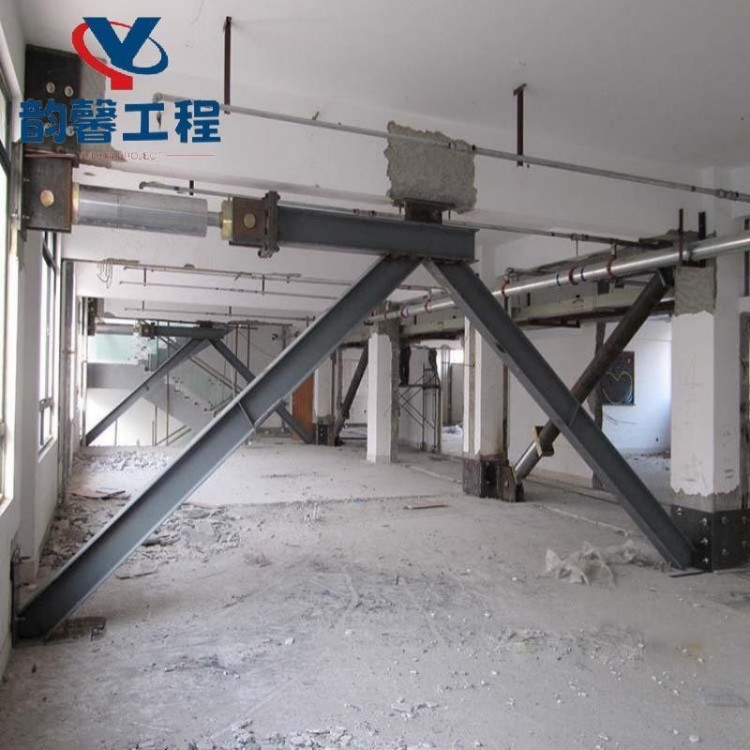
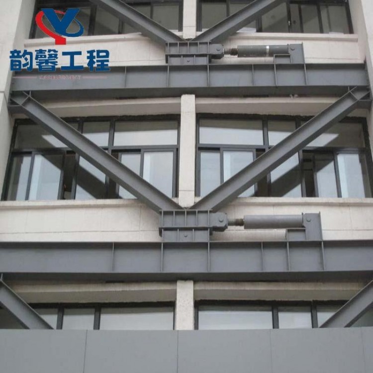
6. Typical Installation Methods for Construction
![]()
![]()
![]()


Un-damped building Damping brace Damping strut
![]()
![]()
![]()


Damper Lateral Support Damper Shear Wall Damper Lasso Type
7. Typical Bridge Installation Method
![]()
![]()


Bridge Pile and Bridge Damper Sliding Wire Damper
8. Factory Acceptance Inspection
Viscous fluid damper, in accordance with the requirements of JG/T209-2012 "Building Energy Dissipation Damper," 20% of the damper units of different types must undergo third-party testing, with a minimum of 2 sets. Factory shipment requires 100% testing. The testing content mainly includes:
(1) Limiting Displacement (F-S)
(2) Regularity (F-V)
(3) Maximum damping force (F-S); additional test items can be added according to Party A's special requirements.
9. Shipment Process
Before shipment, the shipping mark must be indicated on the packaging, which should include:
(1) Manufacturer's Name, Shipper, Contact Information, and Address
(2) Product Name, Specifications, and Quantity
(3) Total number of cartons (quantity) and carton number, bundle number;
(4) Consignee, contact person, contact information, and address.
(5) Rainproof, moisture-proof, and fragile handling labels. Add lifting signs when necessary.
Note: The above markings should be written neatly and legibly in black ink on the front or side of the wooden box.
10. Viscous Fluid Damper Installation
The construction of viscous fluid dampers should comply with the relevant provisions of the national current standards "Technical Code for Safety in High-altitude Operations in Construction" JGJ80-2016 and "Technical Code for Safety in the Use of Construction Machinery" GJG33-2012. In light of the characteristics of the construction and installation of viscous fluid dampers, safety measures should be formulated in the construction organization.
11. On-site Inspection and Acceptance
During the incoming inspection of the viscous fluid damper, the product completion documents and factory inspection report should be available. The steel, welding materials, seals, fasteners, and coatings used in the viscous fluid damper should have quality assurance certificates and comply with the design specifications. The manufacturer of auxiliary supporting components such as brackets or connecting parts should provide raw material certificates and product quality assurance certificates.
12. Installation Time
To avoid accidental contact, bumps, or welding spatter from nearby equipment or structures, the damper installation should be carried out after the surrounding construction is completed.
13. Installation Steps
Before installation, first verify that the installation points, dimensions, node plates, pins, and dampers meet the requirements of the design drawings.
For lighter weight dampers, first connect the damper, node plate, and pin shaft together. Adjust the node plate and embedded part for fit, and install the damper by using bolts or welding. For heavier weight dampers, connect the node plate to the embedded part first, then insert the damper into the center of the node plate and secure it with the pin shaft using bolts or welding.
For those with flanges, the flange end can be secured first, then fastened through the pin bore with a pin.
14. Project Acceptance Software Acceptance (Documentation)
Software Acceptance (Documentation):
(1) Damper Type Inspection Report
(2) Company Qualifications (Business License, Bank Account Opening Permit, and Three Standards System, etc.)
(3) Construction personnel qualifications
(4) Construction organization plans, etc.
Hardware Acceptance (Documentation)∶
(1) Damper Factory Inspection Report
(2) Third-party test report for viscous damper
(3) Weld Seam Inspection Report
(4) Project Handover Documents
(5) Damper acceptance report, damper and support installation acceptance report, etc.
15. Inspection and Post-Maintenance of Viscous Fluid Damper
Our provided viscous dampers are maintenance-free for life, in accordance with the requirements of JGJ297-2013 "Code for Energy Dissipation and Vibration Reduction Technology in Buildings."
The inspection of viscous dampers can be categorized into routine inspections and emergency inspections based on the inspection time or occasion, and into visual inspections and sampling inspections based on the inspection method.
Viscous dampers should be regularly inspected based on the design service life and requirements of the design documents. Under normal operating conditions, a visual inspection is generally required every 10 years or during building maintenance; a sampling inspection should be conducted upon reaching the design service life. Sampling inspections should also be carried out on viscous dampers after they have been affected by disasters such as earthquakes, strong winds, and fires.
During the visual inspection of the viscous damper, observe the appearance, deformation, and other issues of the damper, support, and connecting components. Pay attention to the following appearance, deformation, and other phenomena of the energy absorber during the visual inspection and handle them promptly, as shown in Table 2.
During the sampling inspection of viscous dampers, typical dampers in service should be extracted from the structure for in-situ or laboratory testing of their basic performance. The test content should reflect any potential changes in performance parameters during use, and assess the likelihood of meeting the predetermined service life.
Table 2: Visual Inspection Content and Maintenance Methods for Damper
Serial Number | Estimated content | Maintenance Methods |
1 | Surface leakage of medium in the sticky damper | Replace the damper |
2 | Bolts at the connection of the viscous damper are loose, or weld seams are damaged. | Tighten, re-weld |
3 | Surface of viscous damper and accessories shows dirt, hardening spots, and lumps. | Timely removal |
4 | Surface rust or damage, and protective or fire-resistant coating cracks, peeling, flaking, aging, etc. on shock absorbers and accessories | Cleaning, repairing, refinishing |
5 | Viscous damper or accessory causing bending, local deformation | Replace the damper |
6 | There may be obstructions around the viscous damper that could hinder its normal operation. | Timely removal |


