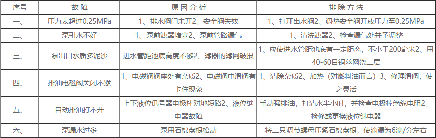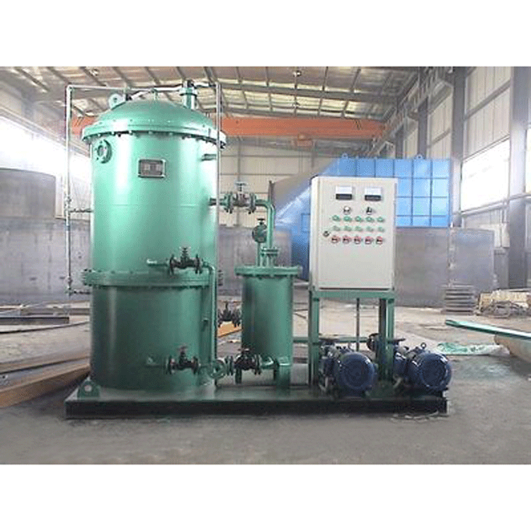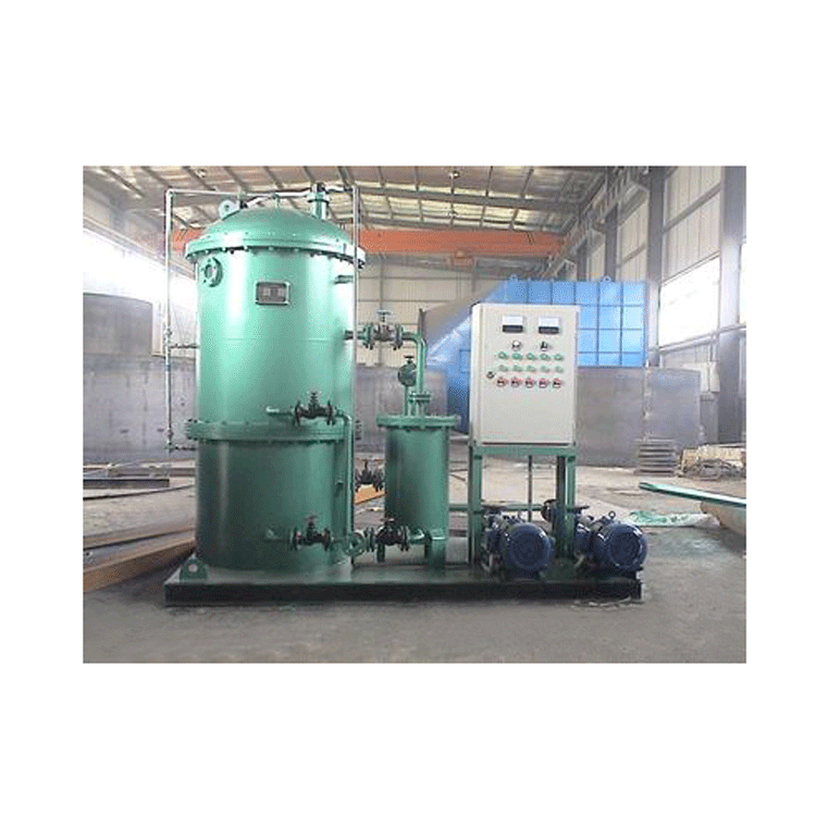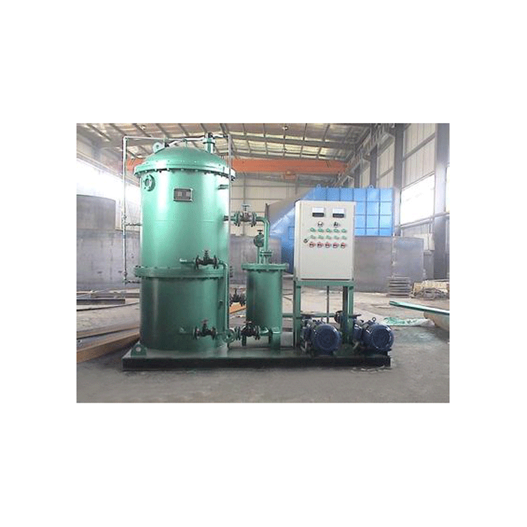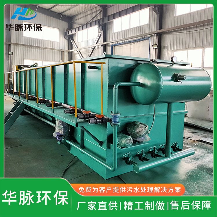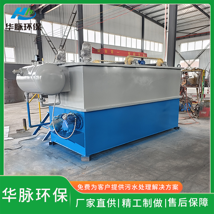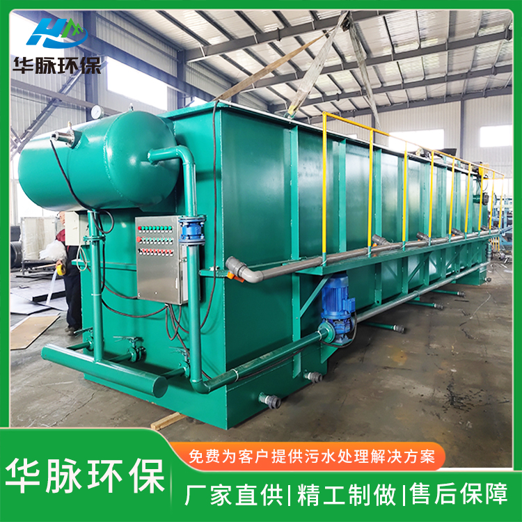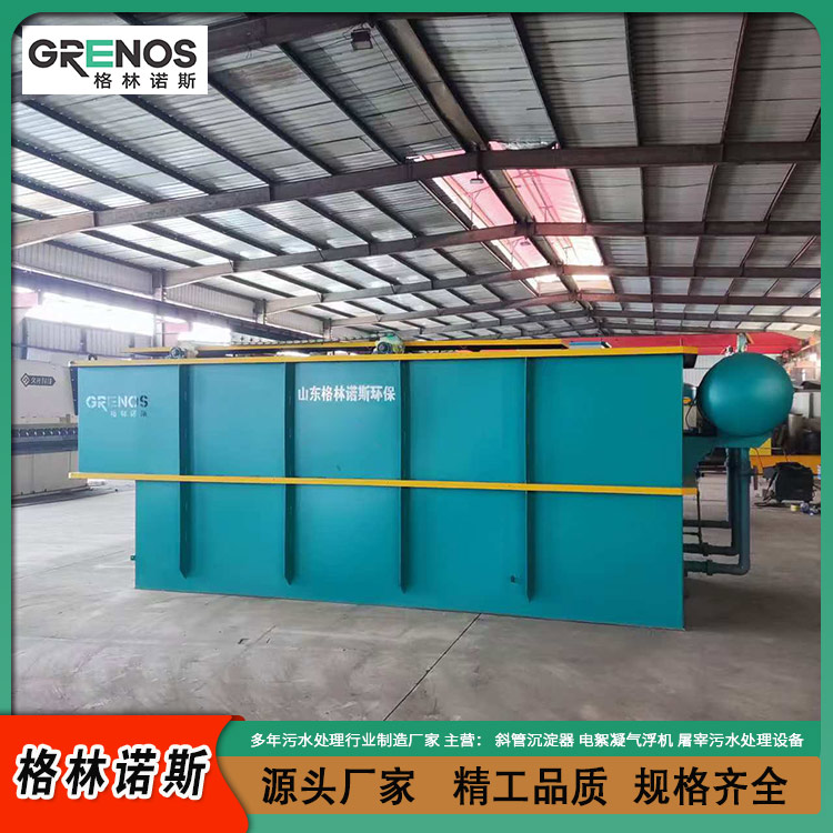


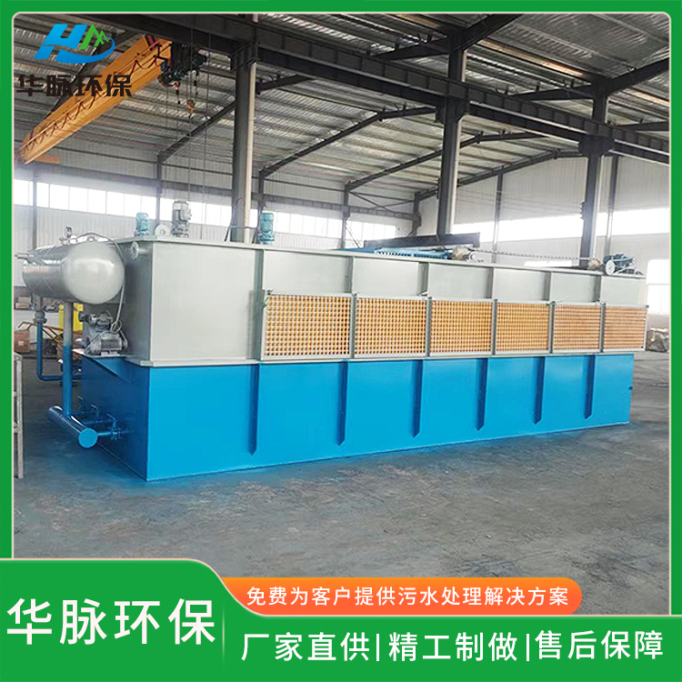


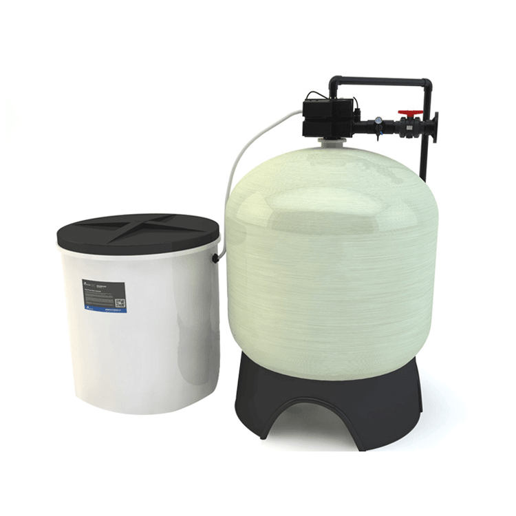

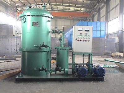
Land-based Oil-Water Separator
This unit is designed based on the principle of gravity separation. Waste oil enters the separation chamber, where, due to the large wetted surface area of the coarse-grained elements and low flow rate, it aggregates into larger oil droplets, which float to the top collection chamber. Oil droplets containing smaller particles sequentially enter the second and third coarse-grained units. The special agglomeration function of the coarse-grained elements causes the remaining fine oil droplets to coalesce into larger droplets before separating from water, rising to the top collection chamber.
Overview
The LYSF land-based oil wastewater treatment unit is suitable for oil, chemical, mechanical, iron and steel, transportation, logistics, and port industries for oil wastewater treatment. The oil product has a specific gravity of 0.84-0.93 mineral oil, but cannot separate oil wastewater in emulsified state. The technical specifications of this unit fully comply with the national standard GB12917-91 for oil wastewater separation units. The effluent oil content after treatment meets the GB8978-96 comprehensive discharge standard for wastewater.
Operating Principle
Wastewater containing oil enters the separator chamber. Due to the large wetted surface area of the coarse-grained components and low flow rate, oil droplets aggregate into larger sizes and float to the top oil collection chamber. Oil droplets with smaller particles sequentially enter the second and third coarse-grained devices. The special agglomeration function of the coarse-grained components causes the remaining fine oil droplets to coalesce into larger droplets before separating from water and rising to the top oil collection chamber. The clear water at the bottom is discharged through the outlet.
The oil sludge accumulated in the secondary oil collection chamber is automatically discharged through the oil level sensor, the automatic oil discharge unit, and the oil discharge valve. From the third stage and beyond, the coarse particle separator belongs to the refined separation system, with very little oil sludge, which can be manually discharged on a regular basis. To separate oil with high viscosity and facilitate its discharge from the oil sludge tank, electric heating devices are installed in the secondary separation chamber, with automatic control to maintain the temperature between 25℃ and 50℃.
Automatically start and stop the pump based on the oil wastewater level in the pond. Users can specify their requirements and configure an UGK-15 float level controller for automatic operation. Additionally, users can install an oil content meter as needed to automatically monitor whether the discharged water meets the discharge standards. Upon reaching the standard, the water is automatically discharged without the need for manual inspection.
Installation Requirements for the Equipment
The installation of this device, generally speaking, should be arranged according to the system diagram; however, during the installation process, special attention must be paid to the following points:
1. Always install the supplied pump inlet filter before the plunger pump.
2. A clear water pipeline should be set up for flushing and maintenance.
3. The oil and wastewater intake on the pipeline of this device should be a certain distance from the bottom of the pool, generally not less than 200 millimeters.
4. The user should install a vacuum gauge on the suction pipe before the pump to monitor the pump's operating condition (user-provided).
5. The water supply pipeline system should strictly prevent air leakage and minimize pipeline resistance caused by elbows and other fittings.
6. The oil discharge pipeline should be as short as possible, and the waste oil tank should be as close and lower than the equipment.
7. The electrical control box of this device does not automatically shut off the pump when it is in a vacuum state to prevent the pump from running dry.
Operation Procedure
4.1 Preparing
(1) Open the valve on the water outlet pipe.
(2) Open the pressure gauge valve.
(3) Open the vent plug at the top of the cylinder.
(4) Turn the first and second oil drain knobs on the electrical control box to the automatic position.
4.2.2 Water Supply
(1) Power on.
(2) Open the fresh water inlet valve and fill with fresh water.
(3) As the clear water enters the cylinder, air escapes through the venting plug located at the top of the cylinder. After the cylinder is filled with water, close the venting plug. At this point, the "Oil Discharge Indicator" should automatically turn off.
(4) Close the water valve.
4.3 3. Oil Absorbing Wastewater
(1) Start the motor, the plunger pump is operating.
Before starting the equipment, ensure the cylinder is filled with fresh water; check regularly by frequently opening the air vent plug.
(3) Heating should be determined based on the temperature of the oil and wastewater and the nature of the sludge oil, e.g., if the water temperature is low (below 20°C) and the oil has a high viscosity (fuel oil), the electric heater should be frequently turned on. Otherwise, it may not need to be activated, but heating in the air is strictly prohibited. (The cylinder must be filled with water.)
4.4 4. Work Completed
(1) Shut off the pump and disconnect the power supply.
(2) Open the clean water valve and fill with clean water for half an hour.
(3) Close the water valve.
(4) Close the outlet pipe valve.
(5) During downtime, ensure that the liquid level in the separator drum does not drop, keeping the drum always filled with fresh water.
Maintain
1. The filter in the pump's feedwater pipeline should be cleaned at least once a week. If the filter mesh is damaged, it should be repaired or replaced with a 60-mesh copper wire mesh promptly.
2. The plunger pump should be maintained annually, including disassembling, cleaning, and inspecting components such as the transmission, pistons, and sleeves. Special attention should be given to the roundness of the nylon balls, their flexibility within the valve seats, and the sealing of the ball valves to ensure the pump's volumetric efficiency.
3. To prevent coarse particle components from clogging, the drain valve should be opened regularly to flush out waste. If the pressure difference between the two cylinders reaches above 0.1 MPa, the device should be promptly disassembled to clean the coarse particle components or replace them.
4. When the cylinder needs to be opened for maintenance, first turn the manual opening position of the first and second-stage oil drainage solenoid valves, drain the residual oil at the top of the cylinder, then open the lower drain valve to empty the remaining water and sludge inside. Clean it thoroughly. Pay attention to the sealing between the coarse particle elements and the water collection cavity during assembly after maintenance. Immediately fill it with clean water after maintenance for wet storage.
Basic Working Principle of Electrical Control Section
This unit is equipped with a J2 electrical control box, powered by 3-phase AC 380V, 50Hz (power supply can also be customized according to customer requirements), with automatic control for oil draining and heating.
The oil drain solenoid valve is controlled by electrode rods. The plunger pump pumps oil and wastewater into the cylinder for oil-water separation. When the separated oil floats to the electrode below the oil level, the electrical signal opens the solenoid valve through the level relay, and oil drainage is automatically initiated. Once the wastewater oil has been drained to a certain extent, due to the continuous operation of the plunger pump, the water level continues to rise until it reaches the upper electrode. At this point, the electrical signal closes the solenoid valve through the level relay, ending the oil drainage.
The heating control is regulated by an electric contact thermometer. Typically, it is set to around 25℃ to 50℃, and the heating will automatically stop if the temperature exceeds the control range.
Automatic oil discharge and heating can be controlled both automatically and manually.
When the oil drainage fails, first determine if it's a fault with the level relay, a low insulation resistance issue with the level sensor, or another problem, and then resolve them accordingly to ensure normal operation.
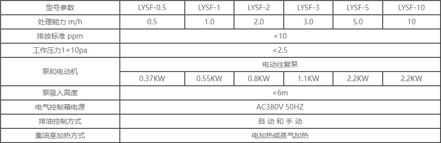
Product Specifications and Key Parameters
Common Fault Causes Analysis and Exclusion Methods