


Germany AUMA OMA Actuator Details
Product Introduction
AUMA NORM (Basic Output Section)
Composition and Brief Introduction of AUMA NORM
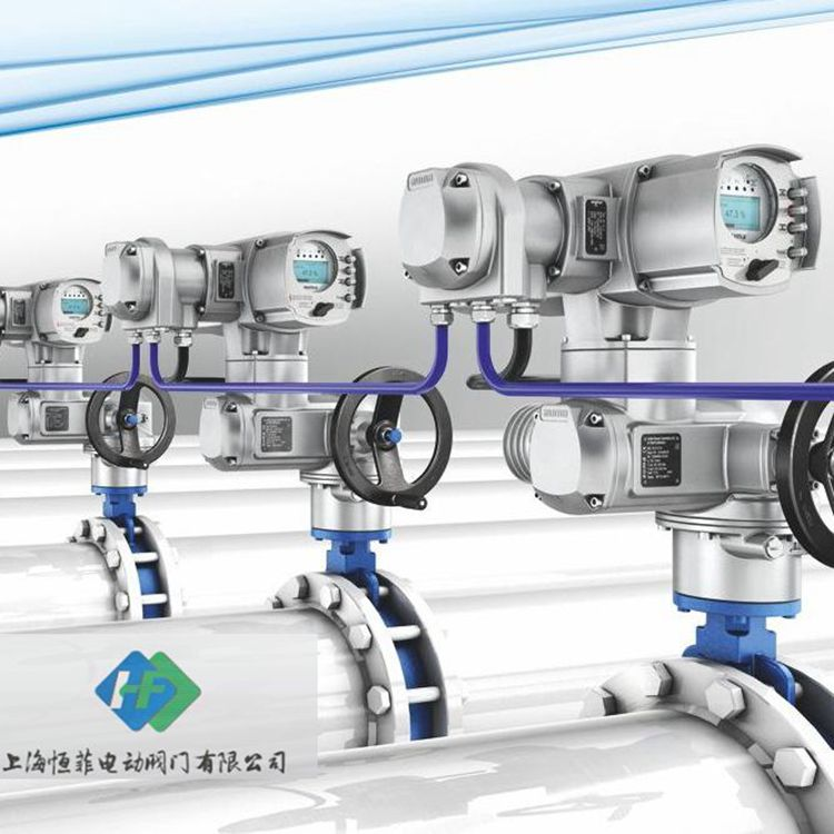
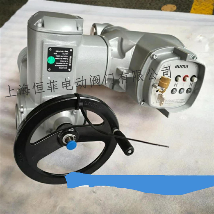
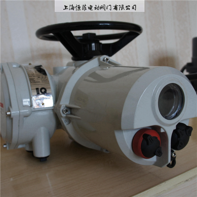
The entire product series of AUMA multi-turn actuators are designed with a unified modular approach. Its standard configuration, AUMA NORM, consists of the following components: 1. Motor 2. Transmission Mechanism 3. Control Unit 4. Electrical Connections 5. Valve Connection Device 6. Manual Mechanism
The transmission mechanism, with worm and worm gear reduction, reduces the motor speed to the required output speed. The electric actuators with AUMA MATIC are composed of: 1. Basic Output Section AUMA NORM 2. Programmable motor integrated control unit AUMA MATIC mounted on the basic output section
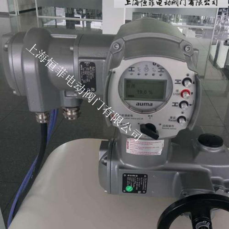
Combining the integrated control unit with the electric actuator offers the following advantages: 1. Compared to wiring for standard actuators without control units, it significantly reduces on-site wiring work, resulting in substantial cost savings 2. Since relays are not installed in distant electrical control cabinets, the motor will immediately stop rotating upon pressure on the torque switch or travel switch, avoiding long delays 3. They can be easily and flexibly integrated into various process control systems or into standardized fieldbus systems, such as: PROFIBUS-FMS, PROFIBUS-DP, INTERBUS-S, or MODBUS-RTU.
The AUMA MATIC motor integrated control unit consists of the following modules: 1. Reversing contactor for controlling the motor power supply 2. Operating and signal circuit board - with primary fuse and relay for transmitting control commands from on-site buttons to the electronic circuit; optional indicator lights are available upon customer request 3. Interface board - with opto-isolators for isolating internal and external signal potential differences, relays, and LED indicator lights 4. Logic board designed with SMD technology - equipped with C-MOS field-effect transistors, providing programming capabilities for internal and external signal connections and the possibility of setting motor control with DIP switches 5. AUMA plug-and-play electrical connectors for connecting the AUMA NORM actuator and the AUMA MATIC integrated control unit 6. AUMA plug-and-play electrical connectors provided for user wiring 7. Field/remote control panel with on-site/remote selector switch and buttons 8. Power supply unit for the entire integrated motor control unit 9. Modular design structure of the AUMA MATIC motor integrated control unit makes configuration changes very easy. The AUMA plug-and-play electrical connectors on the actuator without an integrated control unit (AUMA NORM) are identical to the electrical connectors on the AUMA MATIC integrated control unit. This makes upgrading and modifying AUMA electric actuators very straightforward.
Insulation Resistance: Input terminals to housing / 20 MV; Power terminals to housing / 50 MV; Input terminals to power terminals / 50 MV
WeChat Official Account

Scan to follow Official Account