


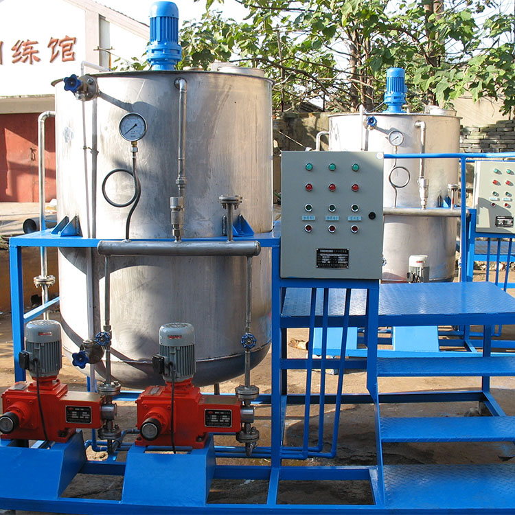

Cooling oil units are indispensable for the lubrication of large and medium-sized mechanical equipment such as steam turbines, fans, coal mills, water pumps, and ship propulsion systems in industrial and mining enterprises.
I. Application:
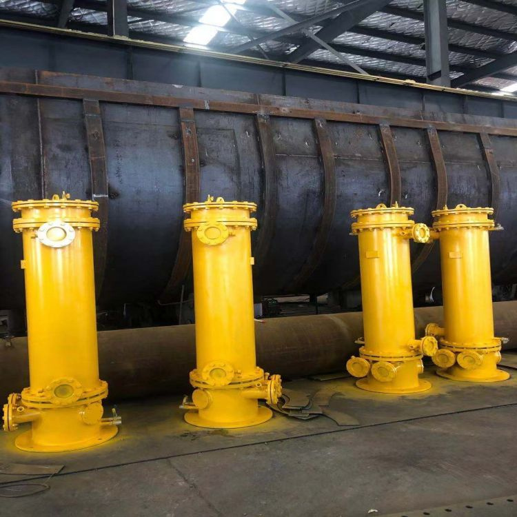
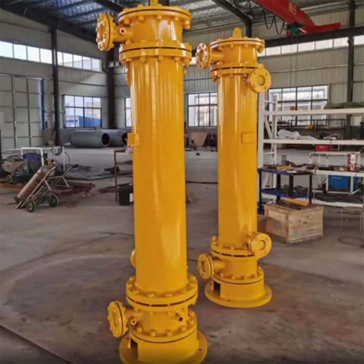
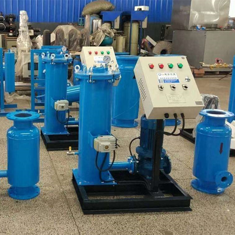
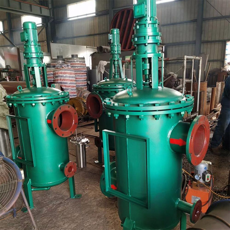
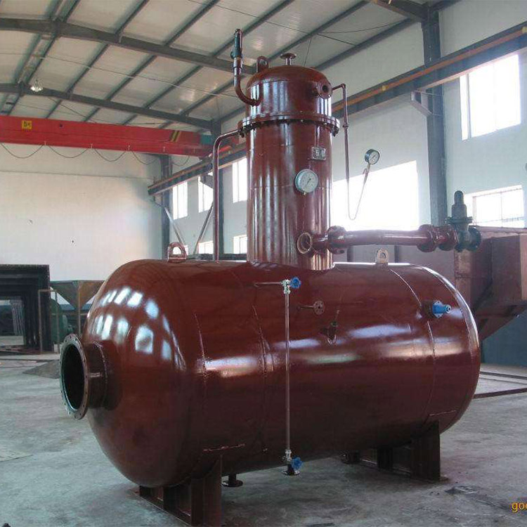
Turbines, fans, coal mills, pumps, and marine propulsion systems in industrial and mining enterprises all rely on oil coolers for the lubrication of large and medium-sized machinery. Based on the advantages of similar products, our company has conducted extensive experiments on the disturbance of the oil-side laminar flow in heat exchangers, successfully developing a new type of tubular oil cooler.
Section II: Product Structure and Working Principle:
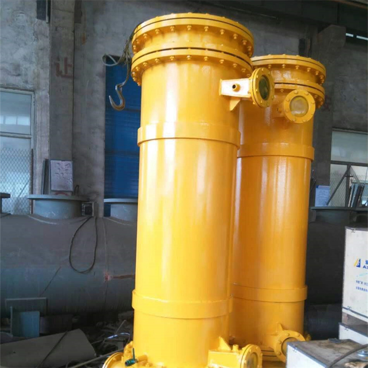
The tubular cooler maintains its flow characteristics with oil passing through the shell side and water through the tube side. The heat transfer coefficient on the oil side outside the tube is 1/10 to 1/20 of that inside the tube, with the main thermal resistance occurring on the oil side. This equipment replaces the traditional arch baffles with swirl guide vanes, with the main principle being: the cooled oil flows through the shell side of the cooler, guided by the swirl guide vanes to rotate and move forward. As it rotates, the oil also scours along the circumference of the tubes. The structural parameters of the tube are the result of optimized selection through multiple comparative tests, offering excellent performance and safety, making it an ideal auxiliary matching product for steam turbine units.
Section 3: Product Features:
Compared to other types of oil coolers, the tubular oil cooler has the following advantages:
High thermal efficiency is 2-3 times that of the plate-type oil cooler.
2. Structurally compact, with a compactness up to 1-2 times that of a plate-type heat exchanger.
3. Low oil resistance: Due to the use of swirling guide plates, oil enters in a tangential flow, which is conducive to fluid operation
4. Long service life and easy installation and inspection: The heat exchange tubes have minimal thermal expansion stress, eliminating common issues like heat exchange expansion failure and leakage. As it retains the tube and shell structure, installation and maintenance are convenient.
Section 4: Product Series Performance and Technical Specifications:
Condensing Turbine Air Cooled Oil Cooler Performance and Specifications
Turbine | Cooling Oil Cooler | Cooling Area | Cooling oil volume t/n | Design Temperature | Highest temperature°C | Design | Supplied with cold oil | |
Enter | Out | |||||||
N1.5 | LY-10 | 10 | 8 | 55 | 45 | 33 | 25 | 1 |
N3 | LY-10 | 10 | 8 | 55 | 45 | 33 | 25 | 2 |
N6 | LY-12.5 | 12.5 | 8.7 | 55 | 45 | 33 | 25 | 2 |
N12 | LY-17.5 | 17.5 | 12.6 | 55 | 45 | 33 | 30 | 2 |
N12 | LY-20 | 20 | 12.6 | 55 | 45 | 33 | 30 | 2 |
N20 | LY-30 | 30 | 27 | 55 | 45 | 33 | 65 | 2 |
N25 | LY-35 | 35 | 30 | 55 | 45 | 33 | 85 | 2 |
N30 | LY-42 | 42 | 36.9 | 55 | 45 | 33 | 102 | 2 |
N50 | LY-48 | 48 | 40 | 55 | 45 | 33 | 112 | 2 |
N100 | LY-55 | 55 | 47 | 55 | 45 | 33 | 135 | 3 |
N125 | LY-60 | 60 | 52.8 | 55 | 45 | 33 | 150 | 3 |
N200 | LY-75 | 75 | 72 | 55 | 45 | 33 | 170 | 3 |
N300 | LY-95 | 95 | 120 | 55 | 45 | 33 | 200 | 3 |
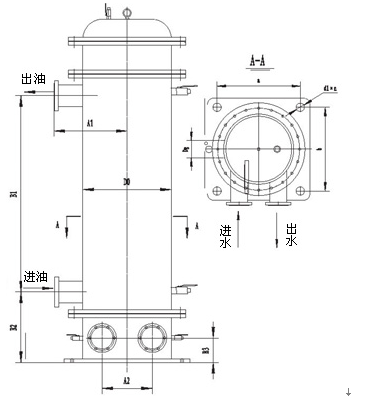
V. Product Dimensions:
Cooling Oil Cooler Model | Outer Diameter of ShellD0 | A1 | A2 | B1 | B2 | B3 | Base Seat | Assume specificationsDg | Weight t | ||
a | b | D1*n | |||||||||
LY-10 | 352 | 340 | 230 | 1050 | 345 | 150 | 380 | 380 | 20*4 | 65 | 0.32 |
LY-12.5 | 352 | 340 | 230 | 1380 | 345 | 150 | 380 | 380 | 20*4 | 65 | 0.86 |
LY-17.5 | 402 | 350 | 240 | 1465 | 345 | 150 | 430 | 430 | 23*4 | 80 | 1.27 |
LY-20 | 402 | 350 | 240 | 1600 | 370 | 150 | 430 | 430 | 23*4 | 125 | 1.30 |
LY-30 | 502 | 400 | 300 | 1150 | 503 | 180 | 525 | 525 | 23*4 | 125 | 1.35 |
LY-35 | 502 | 400 | 300 | 1300 | 503 | 180 | 525 | 525 | 23*4 | 150 | 1.40 |
LY-42 | 502 | 400 | 300 | 1600 | 503 | 180 | 525 | 525 | 23*4 | 150 | 1.47 |
LY-48 | 502 | 400 | 300 | 1700 | 503 | 180 | 525 | 525 | 23*4 | 150 | 1.60 |
LY-55 | 650 | 505 | 330 | 1520 | 503 | 200 | 680 | 680 | 25*4 | 150 | 1.90 |
LY-60 | 650 | 505 | 375 | 1720 | 550 | 200 | 680 | 680 | 30*4 | 150 | 2.42 |
LY-75 | 650 | 505 | 375 | 2100 | 550 | 200 | 680 | 680 | 30*4 | 150 | 2.70 |
LY-95 | 700 | 505 | 400 | 2170 | 605 | 200 | 730 | 730 | 30*4 | 200 | 3.20 |
Section 6: Product Selection
1. Product Applicability
This product series is specifically designed for condensing steam turbines in power plants and various heating steam turbines, and can also be used for lubrication and cooling of power oils in industrial and mining enterprises, such as boiler feed pumps, coal mills, and exhaust fans for air supply and exhaust.
2. Product Model Patterns
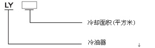
3. Selection Guidelines
Turbine models designed by domestic and international turbine manufacturers are diverse. Based on extensive data collection and computer analysis, our company has compiled various ordering and selection schemes for turbine oil coolers, as shown in the table. For any special usage requirements, please contact our company.
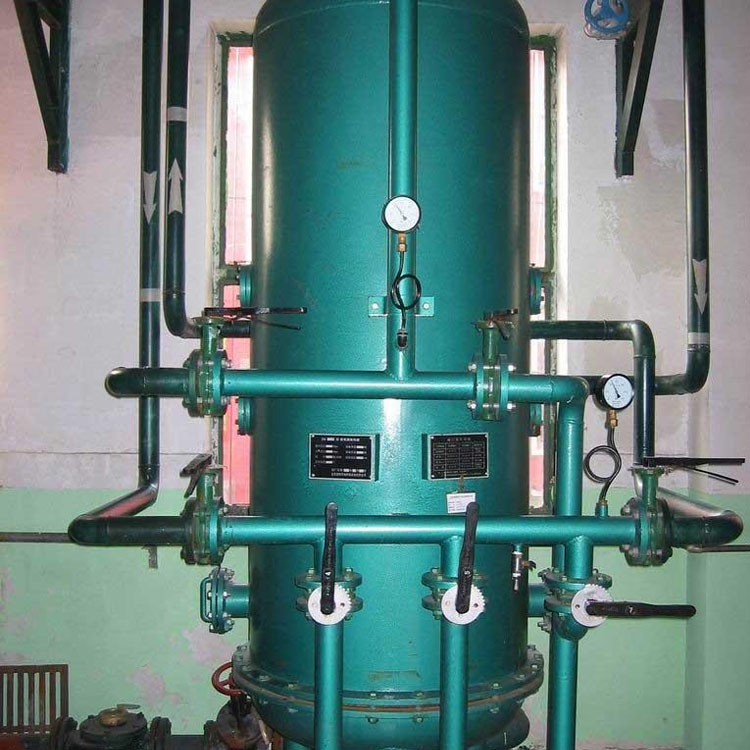
Section 7: Installation of Oil Coolers:
Preparation before installation:
The cooler undergoes a hydrostatic test at 0.6mpa prior to shipment. However, before installation, it should comply with the provisions of "Technical Specifications for Construction and Acceptance of Electric Power Projects" (Turbine Section): "The cooler side should undergo a hydrostatic test at 1.5 times the working pressure, maintaining for 5 minutes without leakage. If an air test is conducted, the pressure should be equal to the working pressure."
2. Coolant Chiller Installation:
(1) The cold oil cooler is supported on a pre-prepared bracket and can meet its dynamic and static load requirements.
(2) Due to the change from an arch-shaped baffle to a swirl guide plate for the support, the cold oil cooler's oil inlet direction is clockwise. Do not install it in reverse.
Section 8: Order Instructions
1. Selecting a cooler, please provide the cooling area.
2. Inlet and outlet oil temperature and pressure, coolant water temperature.
3. Material requirements for heat exchanger tubes.