


Explosion-proof temperature controllers, when used in conjunction with electric tracing heating, can control pipeline temperatures and adjust the set temperature values.ntroller can adjust temperature in response to practical need.
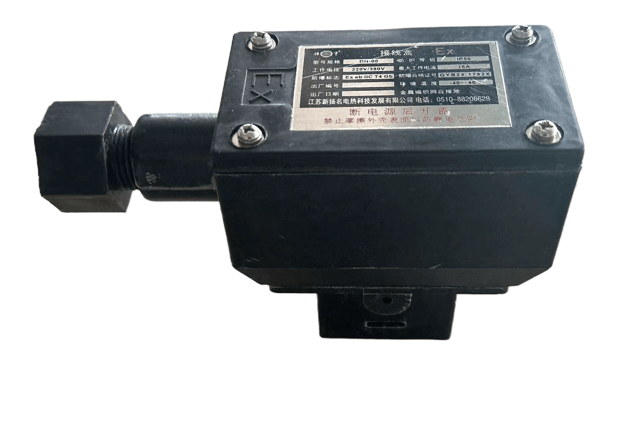
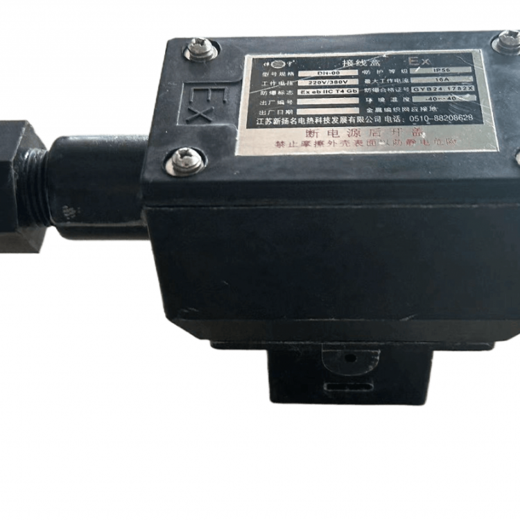
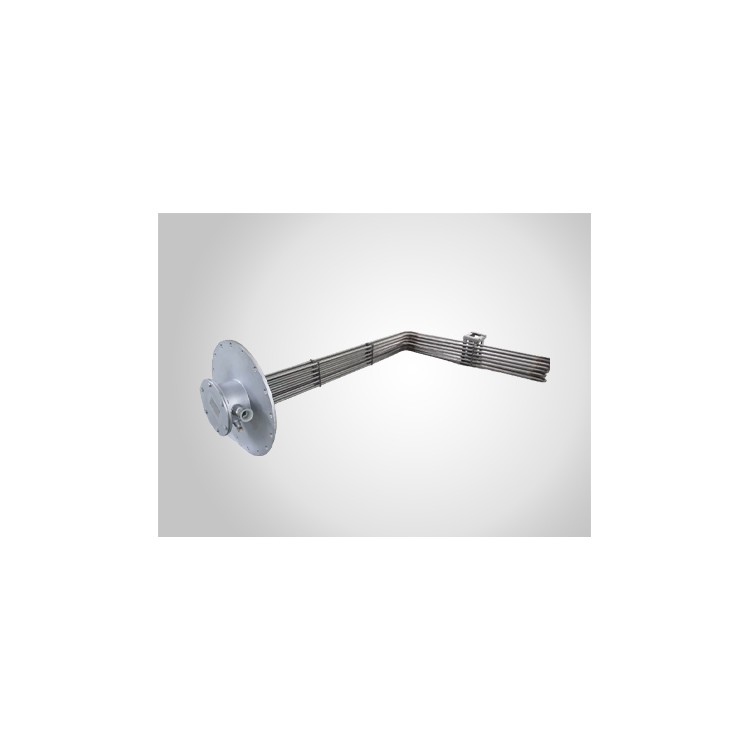
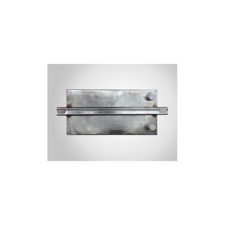
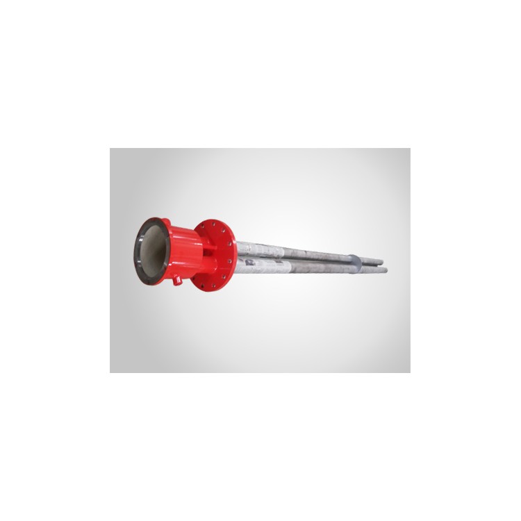
1Product Structure Structure

Explosion-proof Temperature Controllerntroller
2Product Model Catalog Number
Maximum temperature: 120℃-150℃-200℃
Explosion-proof temperature controller
3Key Technical Specifications Technical Parameters(Chart 11)
| Model Catalog number | Intrinsically Safe Rating Explosion-proof level | Operating Voltage Working voltage | Operating Current Working current | Temperature Control Accuracy Temperature control precision | Insulating Resistance Insulation resistance | Electrical Strength Dielectric strength | Protection Level Protection level |
| FWK120/200 | ExedⅡBT4 | 380V/220V | ≤15A | ±2.5℃ | ≥60MΩ | 2000V/min | IP54 |
ø FWK120: Temperature Control Rangentrol range(0~120℃)
ø FWK200: Temperature Control Rangentrol range(50~200℃)
4Single-phase temperature controller installation method Installation
Line 1 connected to A, neutral to N.
connecting phase line to A, neutral line to N
Connect "a" and "n" to the power junction box with wires, then connect them to the electric heating tape.
a terminal and n terminal are connected to heating cable
The temperature sensor probe is attached to the pipeline and sealed in place with aluminum tape.
attaching the temperature probe to the surface of the pipe with aluminum adhesive tape
Adjust the thermostat knob to the temperature you wish to maintain.
adjust the button to the number of practical temperature
5Product Usage and Maintenance Application and Maintenance
Open the junction box cover, unscrew the terminal, thread the incoming and outgoing cables through their respective terminals, and tighten the junction box cover.
Open the cover of the kit, screw off the connection terminal; insert the line through each terminal.
Ensure the cable is connected according to the wiring diagram inside the terminal box, tighten the terminal connectors, and secure the terminal box cover.
Connect the lines as the diagram, tighten the terminal, and then tighten the cover with screws.
Open the temperature adjustment box cover, adjust the temperature to the desired control temperature, and then tighten the cover.
Adjust the temperature according to the practice need.
Secure the temperature controller base in the appropriate position with a clamp and ensure the temperature probe is tightly attached to the area being tested.
Install the temperature controller at the proper position; attach the probe closely to the vessel.
Connect the lead wire to the power box cavity and connect it to the electric heating tape inside. Insert the temperature controller's power line into the power source, check for correctness, and then power on for operation.
Connect the leading-out line with heating cable, connect the temperature controller to the power. Check the connection, and then turn on the power to operate.
The temperature probe can only be installed horizontally or vertically; otherwise, temperature instability may occur.
Keep the probe vertical or horizontal, or temperature will be unstable.
If the junction box is deformed, cracked, or damaged, discontinue use and replace with a new junction box.
If the kit was deformed, chapped, please change a new one.