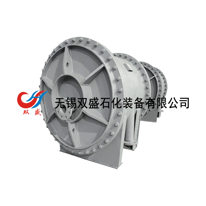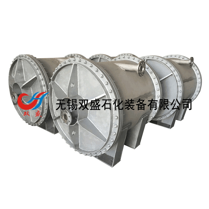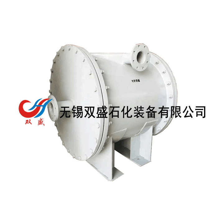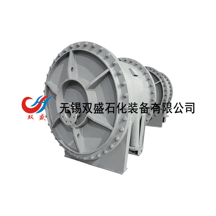

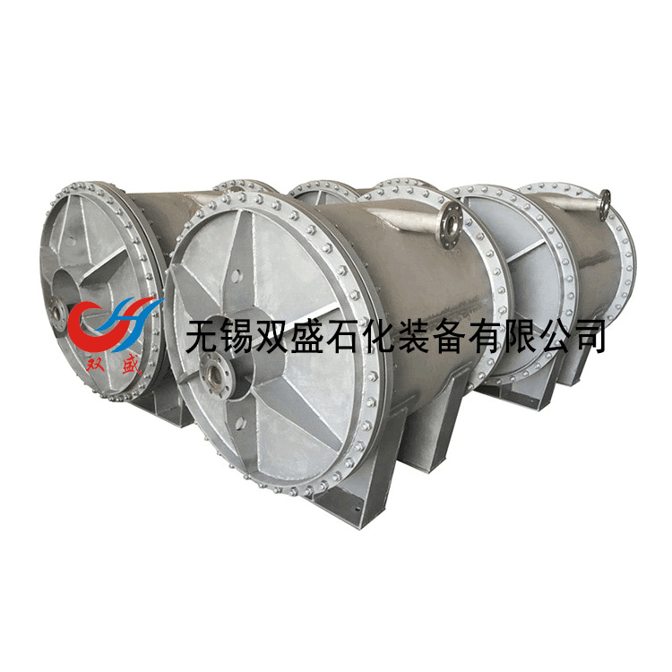
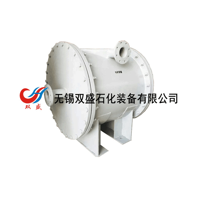


Type III Detachable Horizontal Spiral Plate Heat Exchanger

Structural Features
High thermal efficiency
Due to the spiral channels of the removable spiral plate heat exchangers of Type III, the fluid flows within these channels. Fixed distance columns or stamped distance bubbles are welded to the spiral plates to maintain the width of the spiral channels. Under the centrifugal force of the spiral flow, the fluid can experience turbulence at a lower Reynolds number. Considering that the pressure drop should not be excessive, it is important to reasonably select the channel width and fluid velocity. During design, higher velocities are generally chosen (allowable design velocities are around 2 m/s for liquids and around 20 m/s for gases), which allows for higher fluid dispersion and better contact, thus enhancing the heat transfer efficiency of the spiral plate heat exchangers. In recent years, many domestic units have conducted heat transfer coefficient comparisons between spiral plate and tubular heat exchangers. For example, an auxiliary ammonia condenser for a refrigerator, which originally used a tubular heat exchanger with a heat transfer area of F=75 m², was replaced with a Type III removable spiral plate heat exchanger with a heat transfer area of F=30 m², doubling its efficiency. Similarly, a heater under an ammonia synthesis tower, which previously used a tubular structure with a heat transfer area of F=30.9 m², was replaced with a Type III removable spiral plate heat exchanger requiring only F=15.5 m², also doubling its efficiency.
2. Can effectively utilize fluid head loss
In the III-type removable spiral plate heat exchanger, although there are no sharp changes in flow direction or pulsations, the fluid resistance is generally higher than that of a shell-and-tube heat exchanger due to the longer spiral channels and fixed-distance columns welded to the spiral plates. However, compared to other types of heat exchangers, the fluid resistance in this design primarily occurs due to friction with the spiral plates and collisions with the fixed-distance columns, which can induce turbulent flow. This results in an increased heat transfer coefficient, allowing the III-type removable spiral plate heat exchanger to effectively utilize the fluid pressure head loss.
3. Resistant to clogging
In recent years, numerous studies have focused on the issue of fouling in heat exchangers, as fouling significantly impacts their heat transfer efficiency. In Type III removable spiral plate heat exchangers, since the medium flows through a single channel and the allowable velocity is higher than in other types of heat exchangers, fouling is less likely to accumulate. If fouling does settle in a section of the channel, the cross-sectional area of that section decreases. Under a certain flow rate, a reduced cross-sectional area corresponds to an increased local velocity, which acts as a flushing effect on the fouled area. In shell-and-tube heat exchangers, if fouling accumulates on a heat exchange tube, the local resistance increases, restricting flow and reducing velocity. The medium then diverts to other tubes, rebalancing the resistance across each tube within the heat exchanger. This causes the velocity in the fouled tube to decrease further, making it more prone to fouling and eventually leading to complete blockage. In chemical and oil refineries, the inner diameter of shell-and-tube heat exchangers often experiences fouling, leading to potential blockages. However, in Type III removable spiral plate heat exchangers, due to their self-cleaning action, the rate of fouling formation is approximately 1/10 that of shell-and-tube heat exchangers.
For blockages, overseas commonly use acid washing or hot water cleaning, while domestically, steam blowing is mostly employed, which is more convenient and efficient than hot water cleaning.
4. Utilizes low-temperature heat sources and can control the outlet temperature. To improve the heat transfer efficiency of the Type III removable spiral plate heat exchanger, it is necessary to enhance the heat transfer driving force. When both fluids operate in a fully counter-current manner within the spiral channels, the logarithmic mean temperature difference between the two fluids is greater, which is favorable for heat transfer. Analyzing from the empirical data used in the heat exchanger design, the Type III removable spiral plate heat exchanger allows for a low minimum temperature difference, enabling heat exchange even with a temperature difference of 3℃ between the two fluids. Due to the lower allowed temperature difference, countries around the world utilize this type of heat exchanger to recover low-temperature heat energy.
Type III removable spiral plate heat exchangers feature two longer, uniform spiral channels, allowing for even heating and cooling of the medium, thus enabling control over the outlet temperature.
5. Compact Structure
A 1.5m diameter and 1.8m wide Type III removable spiral plate heat exchanger, with a heat transfer area of up to 200m², and a heat transfer area per unit volume approximately three times that of a shell-and-tube heat exchanger.
6. Sealed structure is reliable
Currently, the used Type III removable spiral plate heat exchanger features welded sealing (irreversible) at the two-channel ends and end cover clamping (removable). The irreversible sealing ensures welding quality while preventing internal leakage between the two media. The removable ends are clamped with end covers, which have an integral sealing plate. As long as the two ends of the spiral channels are machined smooth, it can prevent fluid from bypassing from one side to the other.
7. Small temperature difference stress
The III-type removable helical plate heat exchanger features allow expansion. Due to its two longer helical channels, when the helical plates are heated or cooled, they can extend and contract like the spring in a clock. Each turn of the helix has one side with hot fluid and the other with cold fluid, with the outer turns exposed to the atmosphere. The temperature difference between the helices is not as pronounced as the temperature difference between the tubes and the shell in a shell-and-tube heat exchanger, thus preventing significant temperature difference stress.
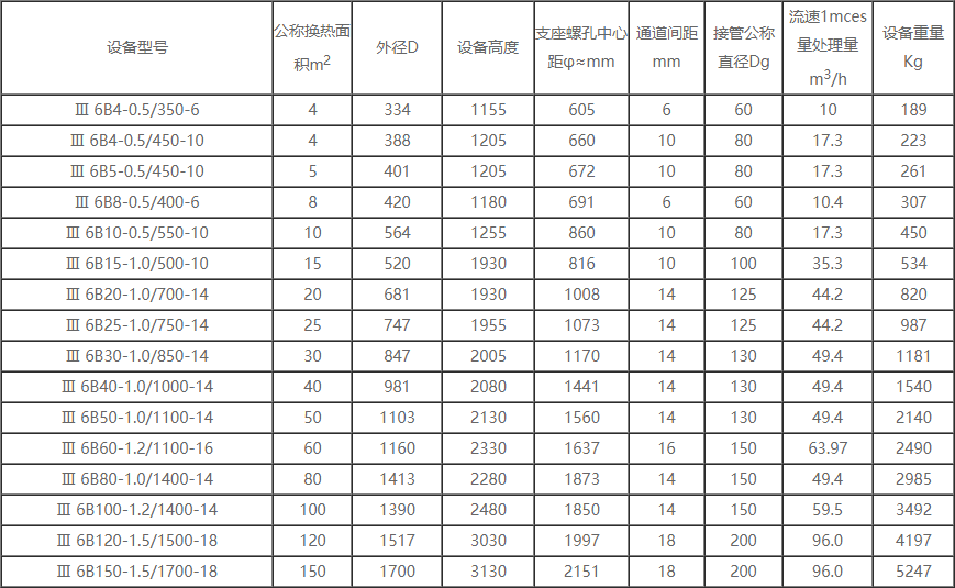
Technical Specifications