
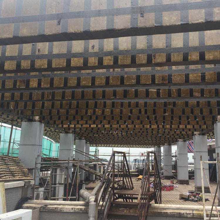


Kindergarten Safety Inspection and Supplementary Delivery Combination Method
Regarding suspicious piles, they should be re-driven to ensure they are fully embedded. This allows the disconnected pile to be re-tightened, providing vertical load-bearing capacity; it also enables the addition of supplementary piles, appropriately inserting sound piles to not only meet the load-bearing requirements of the foundation but also to enhance the seismic load-bearing capacity of the building foundation.
If the pile body is found to be crooked during the pile driving process, with insufficient length, no defects, and no cracks, or if the pile body is crooked due to excavation of the foundation pit but remains intact, the pile body can be partially excavated and then corrected using a jacking system.
1) If there is a significant error in the pile position: the existing foundation planning dimensions cannot meet the standard requirements of the structure. In this case, the pile position error can be corrected by appropriately expanding the foundation area.
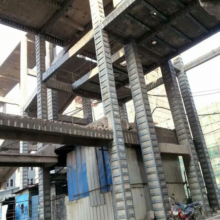
3) Quality Issues with Pile Foundations. In construction, it is advisable to address the uneven quality of pile foundations to prevent subsequent settlement of the pier layout due to foundation issues and to enhance the seismic resistance of the structure. Utilizing integrated pile foundation piers can then improve the overall integrity of the foundation.
1) It utilizes the principle of pile-soil interaction to properly treat the foundation, improving its bearing capacity and more effectively distributing the load on the pile foundation.
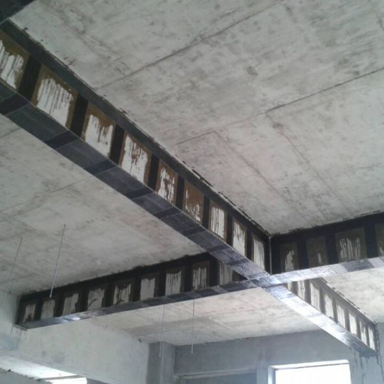
3) Additional cement-soil piles between piles. When the bearing capacity of the piles does not meet the planned requirements, the method of dry-spraying cement into the soil between the piles to form cement-soil piles can be used to form the foundation of the composite soil base.
1) Modify pile types. For example, change from precast square piles to pre-stressed pipe piles.
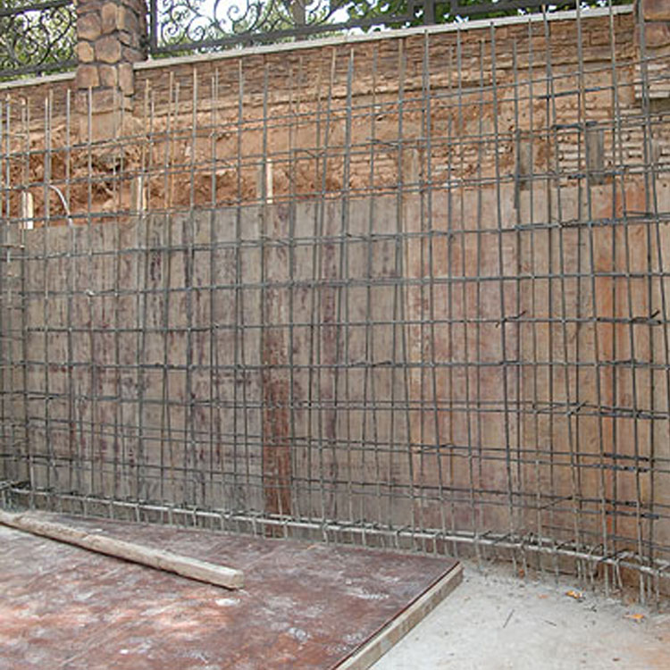
3) Adjust pile positions. In case of encountering solid, small ground obstructions during pile driving that cause the pile to tilt or crack, it is advisable to adjust the pile position and re-drive the pile from scratch. If there are issues with the masonry quality of the safety components for kindergarten, the masonry strength of the component can be reduced. The inspection of the masonry method should check if the up-and-down staggered joints, inner and outer lapping, etc., meet the requirements. The quality inspection of the mortar joints can include joint thickness, fullness, and straightness. The representative value of the joint thickness should be calculated based on the height of 10 bricks of masonry. The fullness and straightness of the mortar joints can be inspected according to the methods specified in the "Construction Quality Inspection Standard for Masonry Works." The detection of masonry errors can be divided into masonry errors and alignment errors.
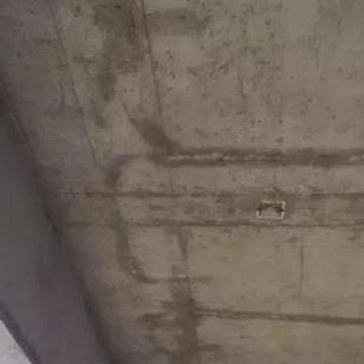
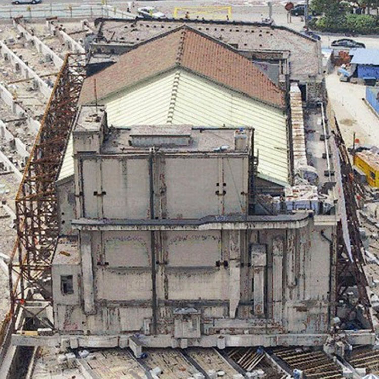
Building Usability Safety Inspection: Most sites of this type are already renovated, rectified, and reinforced. Conducting a detailed survey often has limitations, so the focus of this type of inspection should be on verifying drawings. Key considerations include whether the overall functionality of the building has changed, if the cross-sectional dimensions match the drawings, and if there are any phenomena affecting normal use. For structural inspections, it is generally considered through random sampling of components, with non-destructive testing being the main approach, focusing on analyzing whether the building's structural system and usage status meet the requirements.
The water permeability test of concrete should comply with the following rules: 1. The 6 water permeability specimens in the same group should be separately pressed into the mold and sealed; 2. The water permeability test method according to the current national standard "General Concrete Long-term Performance and Durability Test Methods" should be used to test the water resistance of the specimens in the same group; 3. During the steady pressure process, the water permeation condition of the specimen face should be observed at any time; 4. When water permeation occurs at the end face of a specimen, the experiment of that specimen should be stopped and the time recorded; at this point, the water permeation height of the specimen should be equal to the height of the specimen; 5. If no water permeation occurs at the end face, the experiment should be stopped after 24 hours, and the specimen removed; the specimen should be split in the longitudinal direction to form two halves, and the water permeation contour should be marked with a waterproof pen. Within a range of 60 degrees on both sides of the centerline of the core sample split surface, 10 points of water permeation height should be measured at equal intervals along the water permeation contour with a steel ruler, with readings accurate to 1; 6. The water permeation height of a group of specimens should be calculated according to the following formula: when required, the practical water resistance of concrete with defects and loose areas can be tested according to the above method. The number of water resistance specimens in each group can be less than 6 but should not be less than 3, and the test results of each specimen should be provided.
WeChat Official Account

Scan to follow Official Account