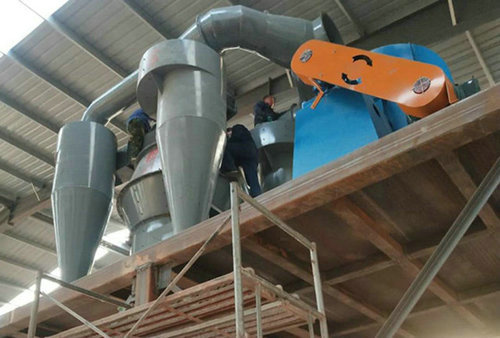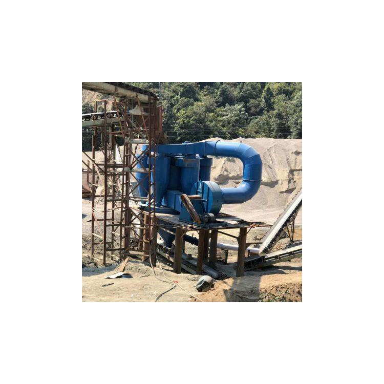


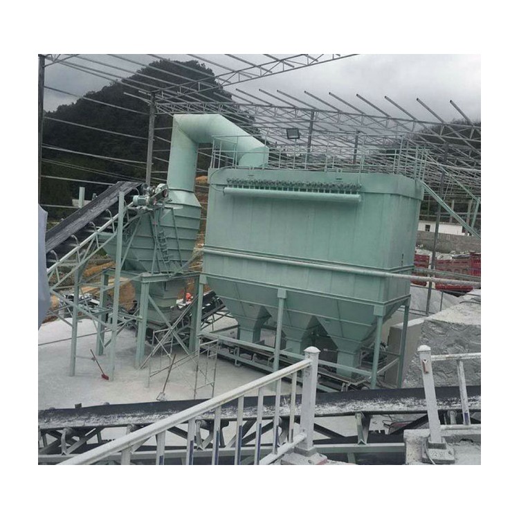
The twin-rotor classifier effectively resists condensation during equipment operation, boasts a wide application range, high powder selection efficiency, and convenient and flexible fineness adjustment, with stable and reliable performance.
Feed Material Granularity: ≤5mm
【Production Capacity】: 20-400t/h
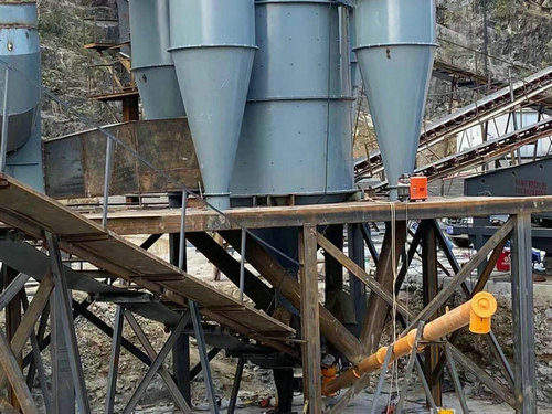
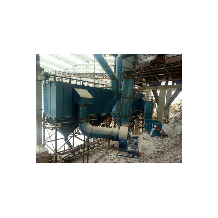
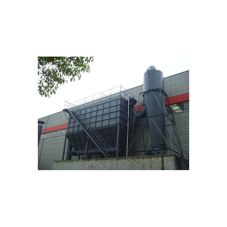
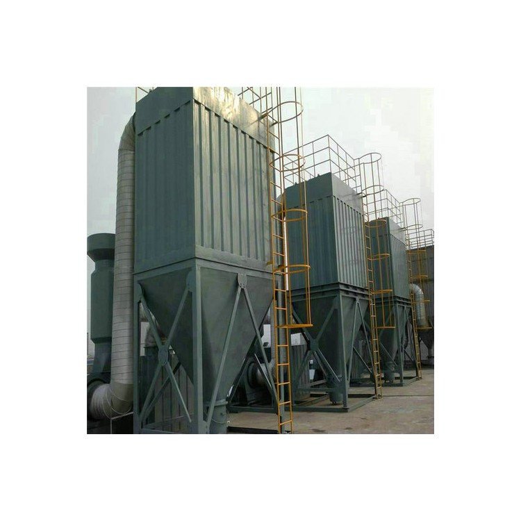
【Application Fields】: Cement powder grinding, sand and stone quarries, mining operations, coal mining, concrete mixing stations, dry mortar, quartz sand, etc.
【Applicable Materials】: River pebbles, granite, basalt, iron ore, limestone, quartzite, dolerite, construction waste, iron ore, gold ore, etc.

Operating Principle
The material leaving the mill enters the inner shell of the classifier through the upper hopper, falls onto the integrated rotor-mounted combination paddle spreader, and is scattered outward due to the high-speed rotation of the spreader. Simultaneously, it is lifted upwards by the ascending air flow generated by the paddle spreader blades, creating a boiling effect on the spreader's paddle blades. Finer particles float upwards in a suspended, dispersed state, while coarser or heavier materials are scattered by the spreader blades and fall along the筒wall, completing the selection process.
2. Below the spreading pan, there is a down-type rotor 10, which rotates with the main shaft to generate eddy currents. These currents re-disperse the coarse and heavy materials that fall along the cylinder wall, causing the fine powder to rise back into the circulating air for re-classification. The coarse powder is then discharged through the dripping device from the inner cone.
3. A cage-type rotor 6 is positioned above the sifter. Inside the selection chamber, the airflow and the material dispersed in the airflow near the surface of the upper cage-type rotor grading ring rotate at high speed along with the grading ring. This results in the formation of a uniform and strong swirling airflow around the grading ring. Within this area, the relationship between centrifugal force and suction force at any position remains constant. The centrifugal force experienced by the material in the airflow can be adjusted by varying the speed of the motor shaft 3. As the speed increases, this force also increases. If the air volume is kept constant, the particle size of the cut product decreases, making the product finer. Conversely, if the speed is reduced, the product becomes coarser.
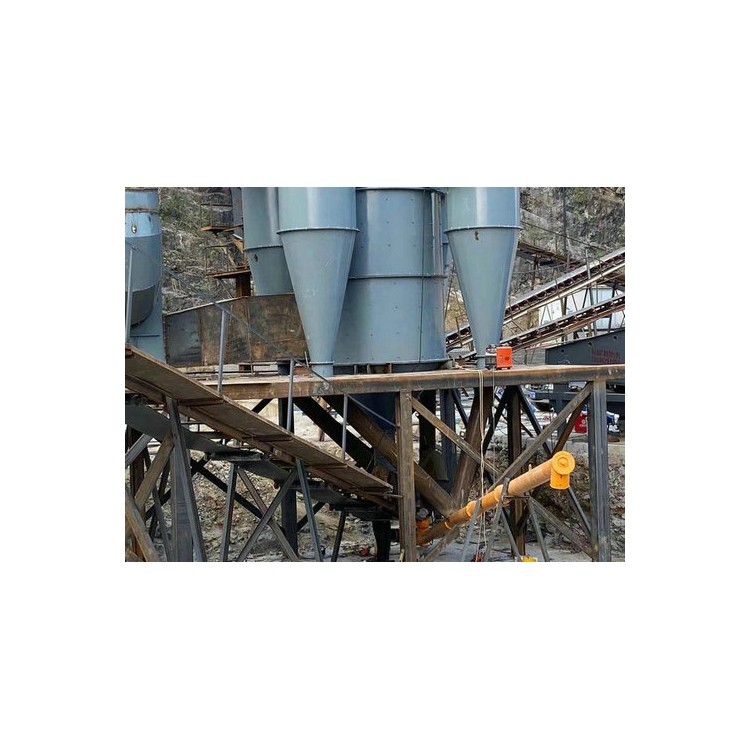
4. After the classifier rotor separates, the fine particles are drawn into the various cyclone dust collectors by the circulating air. Due to the new design of the cyclone dust collectors, which features added guide vanes at the inlet, reflective screens in the inner cone, and a deceleration plate at the bottom, the fluid resistance of the cyclone dust collectors is significantly reduced. The circulating air, under the influence of the guide vanes, enters the cyclone collector at a higher velocity. The velocity suddenly drops in the expanded helical section, accelerating particle settling, and also enhancing the dust collection efficiency of the cyclone dust collectors.
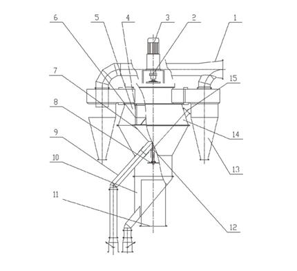
1. regulating valve 2. speed control motor 3. main shaft 4. feed opening 5. diverter pipe 6. upper rotor 7. cyclone chamber 8. selection room 9.撒料盘撒料盘 (dispenser) 10. lower rotor 11. drip device 12. fine powder outlet (single lock air valve) 13. coarse powder cone 14. coarse powder outlet (double lock air valve) 15. fan