


Grated Slot Liquid Distributor; New Integrated Pressure Grating Liquid Distributor
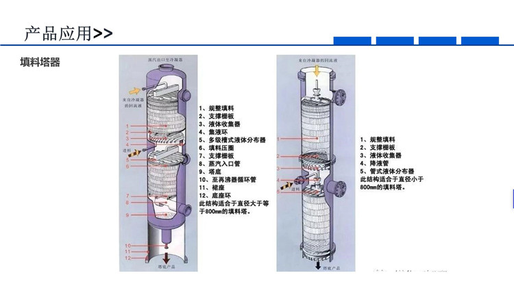
In the chemical industry, gas-liquid mass transfer equipment primarily includes packed towers and plate towers. During the operation of packed towers, the liquid at the top of the tower is evenly sprayed onto the packing surface by a liquid distributor, where it comes into full contact with the rising gas from the bottom. To maximize the efficiency of the packing, it is crucial to minimize the unevenness of the liquid distributor and design a liquid distributor with excellent performance, which is key to enhancing the mass transfer efficiency of the packed tower.
Liquid distributors are categorized by the driving force of liquid distribution, including pressure-type and gravity-type distributors. Common types include pipe-type, trough-type, and perforated disk-type distributors. The two-stage trough-type distributor is widely used in industry due to its large spray density range, large air flow channel, small space occupation, ease of support, and low cost. However, the level of support for the trough, the fluctuation of the liquid surface, and the distribution of liquid volume in the two-stage trough can affect the distribution quality.
The flow rate range of the liquid distributor in a packed tower is expressed by the spray density, defined as the liquid flow rate per unit tower cross-sectional area, i.e., the amount of liquid sprayed per unit time and per unit tower cross-sectional area. The unit is m³/(m²·h). The common spray density range for liquid distributors is 2.5 to 25 m³/(m²·h), but there is currently no liquid distributor suitable for ultra-low spray density conditions, which refer to a spray density less than 0.1 m³/(m²·h).

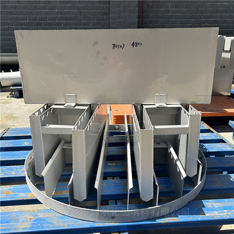
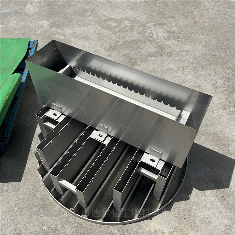
A new type of槽 liquid distributor featuring a discharge pipe, primary槽(3), stabilizing槽(5), secondary槽(11), and a guiding liquid plate(14). The discharge pipe includes an inlet pipe(1) and a distribution pipe(2), with the primary槽(3) housing the stabilizing槽(5) inside. The primary槽(3) side is焊接 with a guiding pipe(4), below which is the secondary槽(11). Each pair of secondary槽(11) is connected by a connecting槽(17). All secondary槽(11) are焊接 together using angle iron(9) or槽 iron. The ends of each secondary槽(11) are焊接 to adjacent secondary槽(11) using angle iron(10). A stabilizing plate(12) is set inside the secondary槽(11). Spray holes(19) are opened on the side of the secondary槽(11), with a guiding liquid plate(16) also mounted on the side. A liquid retaining plate(15) is焊接 to the bottom of the secondary槽(11).
The pipeline mentioned consists of the inlet pipe (1) and the distribution pipe (2). The size of the distribution pipe is designed according to the flow requirements of the distributor.
The primary channel (3) has circular openings (20) at the bottom, with a diameter of 4-10mm. The sides of the primary channel also feature circular openings, and are welded with conduit (4) in parallel. The side circular openings are positioned within the conduit. Due to the secondary channel being longer in the middle and shorter on the sides, the size and quantity of the openings in the primary channel are designed to allow for more leakage in the middle and less on the sides, with the area of the openings being proportional to the cross-sectional area of the secondary channel.
The primary trough is equipped with a stable liquid trough (5), the bottom of which features circular holes (6) with a diameter of 4 to 10mm. Below, there are two rows of circular holes, also with a diameter of 4 to 10mm. The number and diameter of the holes in the stable liquid trough match those in the primary trough. The length, width, and height of the stable liquid trough are all smaller than those of the primary trough.
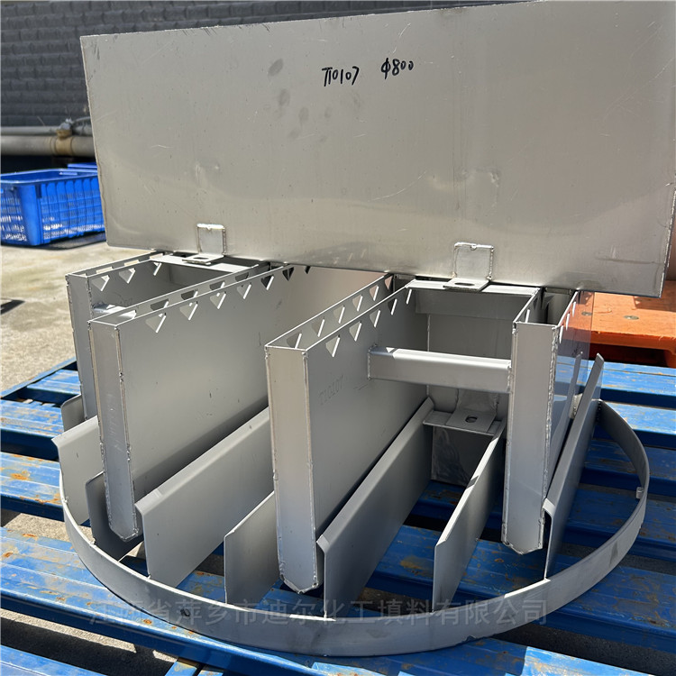
The primary trough is焊接 onto the secondary trough (11), with angle iron (9) or channel iron on both sides of the primary trough. All secondary troughs are connected together via angle iron or channel iron. There is a connecting channel (17) between every two secondary troughs, and each end of the secondary trough is connected to an adjacent angle iron (10).
The secondary channel is equipped with a liquid stabilizing plate (12), which features small holes (18) inside. The diameter of these circular holes ranges from 4 to 10mm, matching the diameter and quantity of the circular holes in the primary channel.
The primary tank's bottom hole location is at the secondary tank's inlet, with the centerline of the side holes on the primary tank aligning with the centerline of the secondary tank below, ensuring that the liquid sprayed down is evenly distributed into each secondary tank. External to the side holes of the primary tank, a conduit (4) is welded for liquid guidance, which extends into the secondary tank, allowing the liquid to flow along the conduit into the secondary tank.
The secondary slot is provided with spray holes (19), which are arranged in three rows. The lower two rows of spray holes have a diameter of 1mm, with a spacing of 50 to 100mm between the holes, and a spacing of 5 to 15mm between the rows. The two rows of spray holes are cross-distributed, suitable for operation conditions with ultra-low spray density. The spacing between the middle row and the upper row is 20 to 30mm. The upper row of spray holes has a diameter of 4 to 10mm and a spacing of 40 to 60mm, suitable for operation conditions with normal and high spray density.
The secondary channel is fitted with a liquid guide plate (14), which is connected to the secondary channel via bolts (13), with a thickness of 2mm.

To enhance the hydrophilic nature of the fluid guide plate surface, the surface is treated to be roughened. The methods of surface roughening are varied, specifically including sandblasting or shot peening the fluid guide plate surface, setting cross-inclined flow patterns, or creating raised round particle bumps.
The liquid guide plate is sandblasted using 1-2mm quartz or metal sand particles; for shot blasting the liquid guide plate, 1-2mm cast steel or stainless steel shot is used.
The liquid guiding plate features a 45° to 60° inclination angle for the guiding grooves, which intersect to form a grid pattern. The grooves are concave, with a depth of 0.5 to 1.5mm, a width of 0.5 to 2mm, and a spacing of 1 to 3mm.
The fluid guide plate utilizes convex dot particles for flow guidance, where the dots in each row are staggered. The inclination angle between every two rows of dots is 30° to 60°, with the height of the convex dots ranging from 1 to 3mm. The radius of the dots is also 1 to 3mm, and the distance between the centers of adjacent dots is 4 to 9mm, with the distance between the centerlines of adjacent rows being 4 to 9mm as well.
To reduce the difficulty of processing, the surface roughening treatment is not applied to the fluid guide plate. Instead, a method of welding a fluid guide thin plate internally to the fluid guide plate is adopted. The fluid guide plate and the fluid guide thin plate are spot-welded together, with the upper part of the fluid guide thin plate fully welded to the fluid guide plate to prevent the liquid sprayed out from the spray nozzle from leaking out through the gap between the fluid guide plate and the fluid guide thin plate.


.jpg)