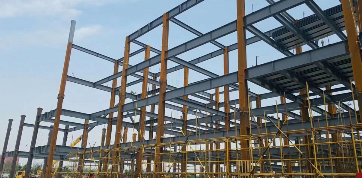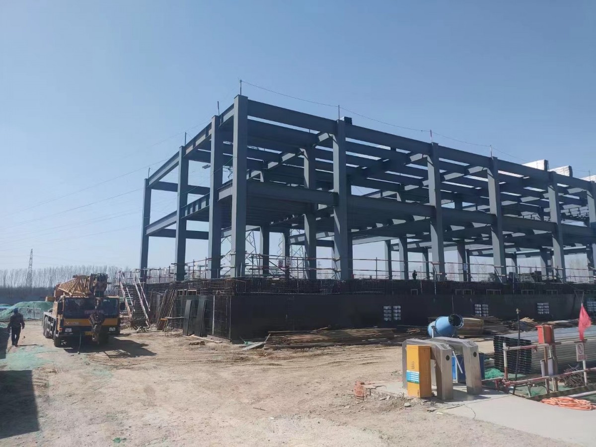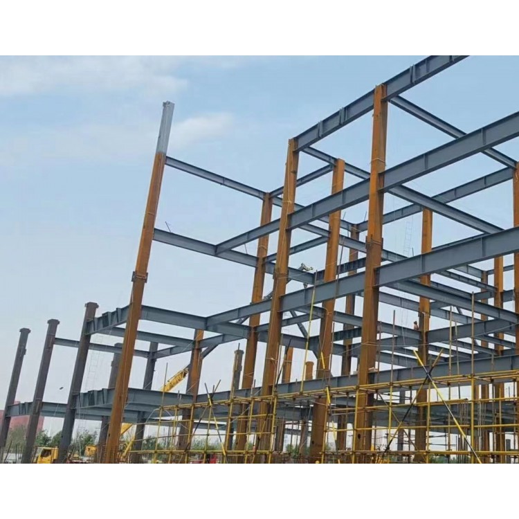

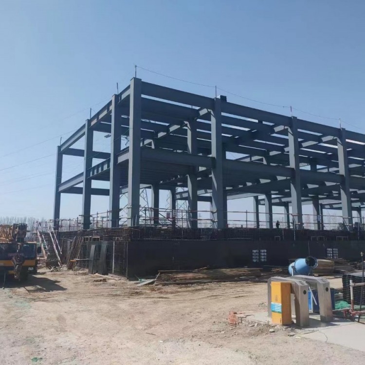


Structural Steel Fabrication
One: Pattern Making and Cutting to Size
1.Pattern making and material marking duties
Pattern making is a process in the manufacturing of steel structures.,Only accurate sample sizes are available.,Only then can we avoid errors in subsequent processing procedures.,Guarantee the quality of the entire component.
The sampling includes::Verify the installation dimensions and hole spacing of the patterns.;Please provide the Chinese content you would like translated into American English.1∶1Release point of the master sample;Verify the dimensions of all parts;Manufacture samples and patterns for cutting, bending, and drilling dimensions.
Pattern making,Please provide the Chinese content you would like translated into American English.1∶1The proportion is plotted out on the layout table using geometric drafting methods.;Patterns checked and verified for accuracy.,Fabricate samples and patterns from steel plates;Please indicate the work number, drawing number, part number, quantity, hole diameter, etc. on the samples and patterns.;Then, cut materials using the patterns and templates.
Numbering materials,Inspect and verify materials,Mark cutting, drilling, and other processing locations on the material,Identify part numbers,As shown in the figure6-16Shown. Patterns and samples should be properly stored.,Until the project is completed.
2.Caution for layout and numbering
1)Pattern making,Consider the machining and planing allowances.,Welded components must be released with the required welding shrinkage as per the process specifications.
2)Cut to size based on the ingredient list and sample.,Minimize material usage as much as possible.,Provide cutting allowances according to the cutting method
2. Cutting
Methods of steel cutting for blanking include shearing, punch cutting, saw cutting, and gas cutting, etc.,The method of construction should be determined based on specific requirements and actual conditions. The cut steel shall not have lamination.,No cracks are allowed on the cross-section.,Remove burrs, slag, and splashes from the切口. The allowable deviation for gas cutting and mechanical shearing should comply with the specifications.
1.Gas Cutting
Oxy-fuel cutting utilizes the high temperatures produced by the combustion of oxygen and acetylene to melt steel.,Blow away slag using gas pressure,Form a seam,Achieve the purpose of metal cutting.
2.Mechanical Cutting
1)Sawing machine.
2)Grinding wheel cutting machine.
3)Shears, profile shearing machines.
3.Plasma Cutting
Plasma cutting is suitable for cutting materials such as stainless steel, aluminum, copper, and their alloys.,High cutting temperature, strong flushing power, excellent cutting edge quality,
Small deformation, capable of cutting any high melting point metal materials.
Section 3: Correction and Shaping
1.Correction
During the钢结构manufacturing process,Due to the presence of material deformation, cutting deformation, welding deformation, and transportation deformation.,It will affect the fabrication and installation of the components.,Correction involves creating new deformation to offset the existing deformation. The correction of section steel is categorized into mechanical correction, manual correction, and flame correction, etc.
2.Bend forming
Cold bending process methods include rolling bending on a round machine,Press bending, top bending, and draw bending on press machines.
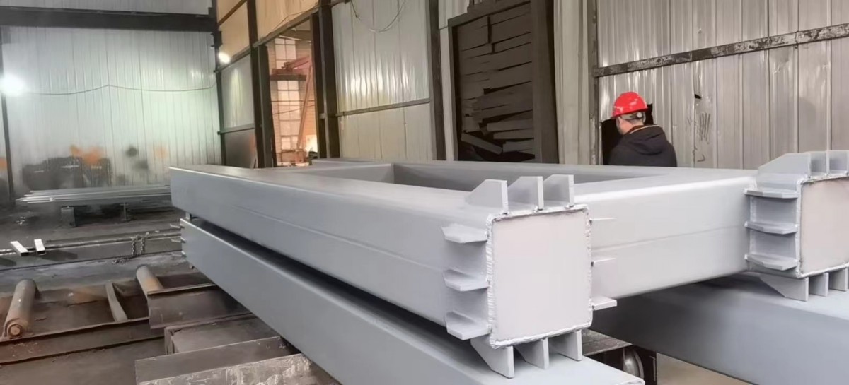
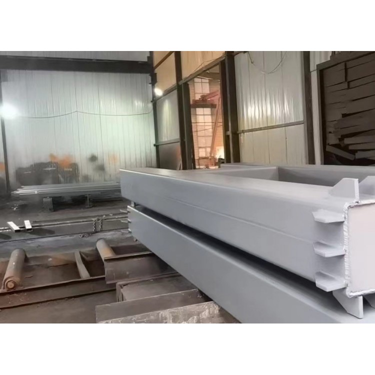
Four: Edge Processing
In steel structure manufacturing,Sheet metal edges after shearing or gas cutting,The internal structure will change. To ensure the quality of critical components such as steel beams or heavy-duty crane beams.,Edge processing is required.,The slicing volume should not be less than2mmIn addition.,To ensure welding quality,And considering the accuracy of assembly,Grind the edges of the steel plate.(Or chopped)Bevel.
Five, Hole Making
Hole making typically involves two methods: drilling and punching.Drilling is a widely used method in the manufacturing of steel structures.;Punching creates holes using a punching machine's shearing force.,Poor bore quality,Less commonly used in steel structure fabrication.
Drilling includes manual drilling and machine drilling. Manual drilling is commonly used for smaller diameter holes in thinner materials. Drilling is convenient and quick.,High precision.
In addition to drilling,There are operations such as boring, countersinking, and reaming. Boring involves enlarging existing holes to the required diameter.;Boring is the process of enlarging a pre-drilled hole in a workpiece.;Boring is the process of finishing a pre-machined hole.,Enhance hole surface roughness and precision.
Six, Assembly
Assembly, also known as assembly or assembly.,The processed parts are assembled into individual components according to the construction drawings.The size of steel components should be determined based on transportation routes, site conditions, the lifting capacity of the installation unit's equipment, and the allowable structural load conditions.
The assembly shall comply with the following requirements.:
1)The assembly of steel components should be conducted on a platform.
2)Preliminary assembly sequence list must be prepared,Proceed in order of the list.
3)Assembling,To fabricate according to the part's processing number;Symmetrical parts should pay attention to orientation.,Avoid mix-ups.
4)For larger-sized, more complexly shaped components,Break down into several simple components before assembling the entire assembly.
5)Assembled components should be numbered according to the drawings.,The item number and location should be clearly and easily identifiable.
Section 7: Welding Operations
1.Selection of Welding Methods
Welding is one of the primary methods of connection used in steel structural fabrication and installation.,Widely used is arc welding.;In arc welding, wire arc welding, submerged arc welding, and gas shielded welding are the main types.;In certain special occasions,It must be used for electroslag welding.
2.Welding Process Key Points
(1)Welding Process Preparation: Determine the welding method, welding parameters, and specifications of electrodes, welding wires, and fluxes.
(2)Determine the Welding Position for Welding Rod Arc Welding - The relative positions of welding rod arc welding during welding include flat welding, vertical welding, overhead welding, and horizontal welding.,As shown in the figure6-17As shown.
(3)Select the type of welding joint
Weld joint forms include butt joints and corner joints. The construction requirements for the plate edge profiles of butt joints are listed in the table.6-2。
(4)Welding Rod Baking
Welding rods must be baked before use.,Baked goods should be stored in an insulated container for on-demand access.
(5)Positioning weld
Ensure accurate positioning of parts during assembly and assembly of welding structures.,Position welding must be carried out first. The length and thickness of the position weld should be determined by calculation.,Current ratio improved over formal welding10%~15%The position of the spot weld should be avoided as much as possible near the ends, corners, or other stress concentrations of the component.
(6)Pre-weld Heat Treatment
Preheating can reduce the cooling rate of the heat-affected zone.,Prevent the occurrence of delayed weld cracking. The preheat zone is on both sides of the weld seam.,Each side width is greater than the weldment thickness.1.5Multiple times,And not less than100mm。
(7)Determination of Welding Sequence
Generally, start from the center of the welded part and expand outward.;Pre-weld large contraction weld joints,Small post-welding shrinkage weld;Attempt symmetrical welding;Weld joints intersecting,Pre-weld the longitudinal seam.,Allow to cool to room temperature,Re-weld the transverse weld seam;When the steel plate is thick, it should be welded in layers.
(8)Post-weld heat treatment
Post-weld heat treatment primarily involves dehydrogenation of the weld seam.,To prevent the formation of cold cracks. Post-weld heat treatment should be conducted immediately after welding.,Insulation time should be determined based on the board thickness, with each25mmSheet thickness1hConfirmed. Preheating and post-heating can both be carried out using a radiant flame gun.
3.Weld joint quality inspection
(1)Visual Inspection
The weld waves on the welding metal surface should be even.,No cracks, incomplete fusion, slag inclusions, weld spatter, undercut, burn-through, arc pits, or other defects are allowed.,Weld joint location and dimensional shapes must comply with the construction drawings and the "Construction Quality Acceptance Specification for Steel Structure Engineering."(GB 50205)Specifications required.
(2)Non-destructive Testing
Non-destructive testing involves using detection equipment to identify internal defects in weld metal.,A non-destructive inspection method for welds, typically including X-ray and ultrasonic testing.
Section 8: High-tensile Bolted Connection Construction
High-strength bolted connections are one of the primary joining methods for steel structures, currently on par with welding.,Its features include easy installation, detachable and replaceable, even force transmission, rigid joints, high bearing capacity, high fatigue resistance, nuts that are not easy to loosen, and a safe and reliable structure.
1.General requirements
1)High-tensile bolts prior to use,Perform a re-inspection of all its performance specifications in accordance with relevant regulations.,Inspection and approval required before use. Handle with care during transportation.,Prevent damage.
2)When storing high-tensile bolts on the construction site,Store in a dry, well-ventilated, rainproof, and moisture-proof warehouse.,Must not be stained.
3)Installation,Please retrieve the bolts according to the day's required quantity. Any bolts not used on the same day must be returned to the container and properly stored.,Do not litter or dispose of carelessly.
4)Install high-tensile bolts,Surface contact must be free of burrs, iron filings, oil stains, and welding spatter. The friction surface should be dry.,No condensation, frost, or snow accumulation,No installation during rain.
5)Torque a bolt to a specified tightness with a torque wrench.,Perform daily calibration of the torque wrench before starting work.,Use only after certification.
2.Installation process
1)High-tension bolts on a connector should be installed starting from the center of the bolt cluster.,Expand outward,Tighten each individually.
2)Joints that feature both high-tensile bolted connections and welding.,Please construct in the sequence of first bolting and then welding.
3)High-tensile bolts should fit freely into the bolt holes.,When a layering error occurs,Permitted to enlarge holes with a tap. While enlarging holes:,Ferric particles must not fall between the board layers. The number of expanded holes should not exceed the bolts for one junction.1/3The diameter of the expanded hole should not exceed1.2d(dFor bolt diameter)Absolutely no gas cutting is allowed for expanding high-tensile bolt holes.
4)The insertion direction of multiple high-tensile bolts in a single connector should be consistent. The chamfered side of the washer should face the bolt head and nut.,The rounded end of the nut should face away from the washer.,Do not reverse mount.
5)High-strength bolts after being tightened,Exterior bolt threads should be exposed.2~3Buckle,Among which, there may be10%Exterior exposed bolts and nuts1Knit or weft4Knit.
6)Common tightening methods include torque tensioning.:Torque wrench with direct torque value display,Initial torque is a fraction of the final torque.60%~80%The purpose is to achieve full tightness between the steel plates of the joint through initial twisting.;Final tighten is to securely fasten the bolt.