


Image and Text Details Product details
Sampler Cooler
I. Product Overview
Cooling取样 cooler for water and steamFor power plant, steel smelting, chemical, textile, dyeing and printing, and boiler rooms, water and steam sampling cooling and testing are used. Product series include: steam sampling cooler, boiler water sampling cooler, make-up water sampling cooler, condensate sampling cooler, and blowdown sampling cooler. Water and steam in boilers and thermal systems are usually at high temperatures, which are not conducive to sampling and measurement. Sampling coolers can cool boiler water down to (30-40°C) and convert steam into water, then cool it down to (30-40°C), facilitating safe sampling by operators and achieving the cooling medium temperature below 30-40°C to meet the standard DL/T 457-91 of the People's Republic of China's power industry, and meet the requirements for sampling and testing.
II. Technical Requirements
1. The coolant flow rate of the sampling cooler is 500-700mL/min, and the cooling medium temperature can be reduced below 30°C.
2. The cooling tubes of the sampling cooler are all made of stainless steel pipes, carbon steel or copper pipes cannot be used to prevent the sample from being contaminated by the metal corrosion products of the cooling tubes.
3. The cooling tubes of the sampling cooler can be designed as a single coil or a double coil (designed based on medium parameters and installation space).
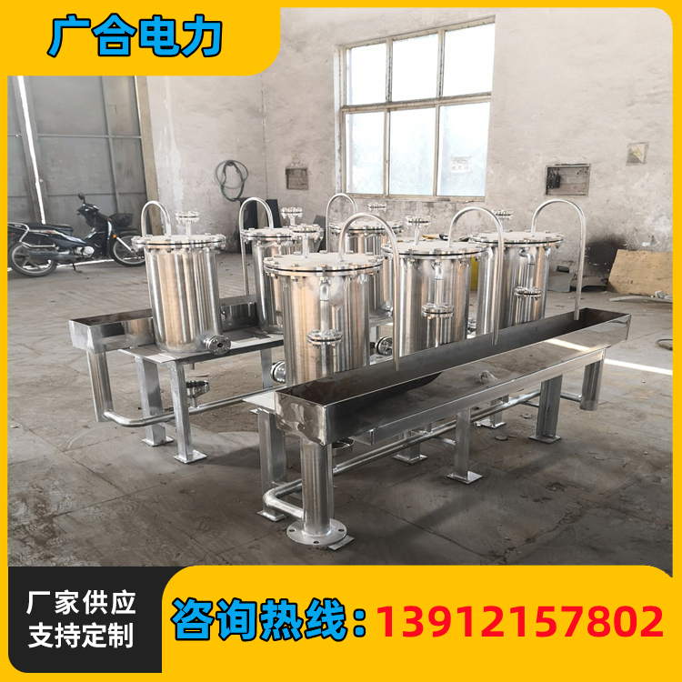
4. The Sampling Cooler is designed for sampling high-temperature liquids and gases, featuring a compact structure, high heat transfer efficiency, easy cleaning, and long service life. The sampling tube employs a spiral serpentine coil structure and is made of stainless steel, offering high-temperature resistance, corrosion resistance, long service life, and non-contamination of the sample. Depending on the distribution and concentration of the sampling points, it is designed to accommodate either a single Sampling Cooler or a modular Sampling Cooler, facilitating simultaneous sampling of steam, boiler water, condensate, make-up water, and deaerator outlet water.
5. Sampling point distribution locations
Project | Sampling Point Name | Sampling point location |
Water Supply | Deaerator water supply pipeline | Each outlet pipe for the water tank |
| Regenerative Feedwater Heater Import | Energy-saving boiler imports | |
| Boiler Water | Segmented Evaporation Boiler Water | As per boiler specifications |
| Saturated Steam | Segmented evaporative boiler saturated steam | |
| Reheater | High and low temperature reheated steam | |
| Overheater | Overheated steam, desuperheated steam | |
| Condensate | Segmented Evaporation Boiler Condensate | Condensate Outlet |
Hydrophobic | Thermal descaler | Thermosyphon Drain Outlet |
| Drain tank draining | Water separator drain outlet | |
| Heating Element Drain | Heater bleed outlet | |
| Produced Recycled Water | Return Water Tank Return Water | Each return pipe and outlet |
| Reducing Water | Self-cooled condensate | Self-cooled condensate drain pipe |
Section 3: Product Order Instructions
1. Offer sampling medium for temperature, pressure, steam, water, and steam-water mixture
2. Cooling medium temperature and pressure
3. Material requirements (normally, cooling tubes are made of stainless steel, and the housing is carbon steel)
4 Connection methods and whether a combination type is required
5. Various import/export connection methods (flanges, welding, etc.).
FourSampling Chiller Product Specifications and Models
| Model and Specification | Stainless steel coil internal pressure: MPa | Suitable for temperatures of °C | Cooling Area m² | Cooling Water Parameters |
| QY-108/0.22 | ﹤10.5 | 100≈580 | 0.22 | Water temperature < 32℃ Water Pressure: 0.2~0.8 MPa Flow Rate ≥ 1.5 t/h |
| QYL-133/0.26 | 0.26 | |||
| QYL-159/0.32 | 0.32 | |||
| QYL-219/0.38 | 0.38 | |||
| QYL-254/0.45 | 0.45 | |||
| QYL-273/0.54 | 0.54 | |||
| QYL-290/0.66 | 0.66 | |||
| QYL-273/0.69 | ﹤10.5 | 0.69 | ||
| QYL-290/0.72 | 0.72 |
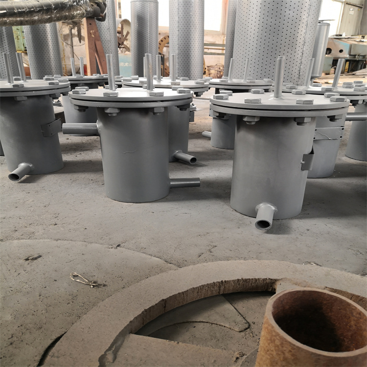
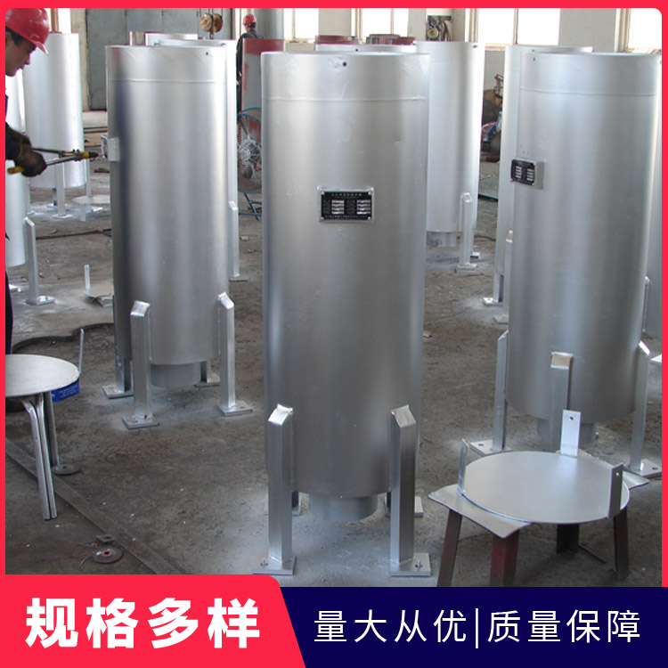
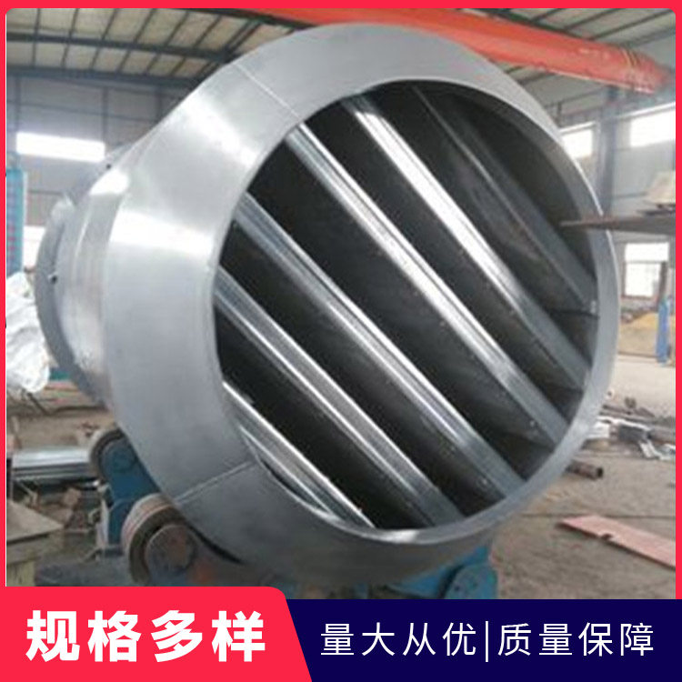
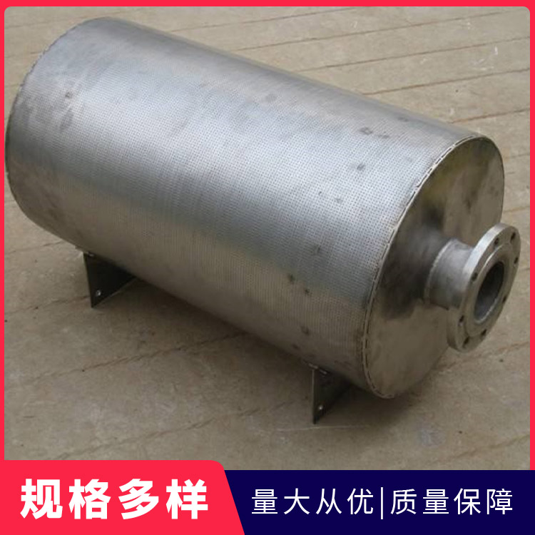
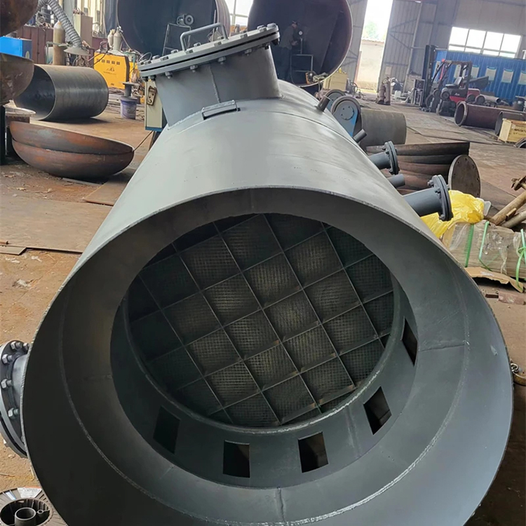
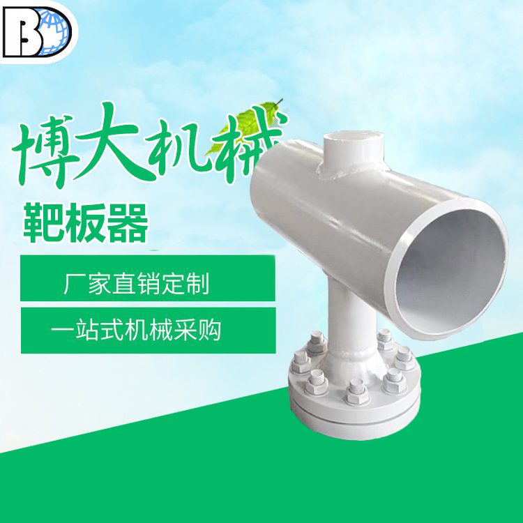
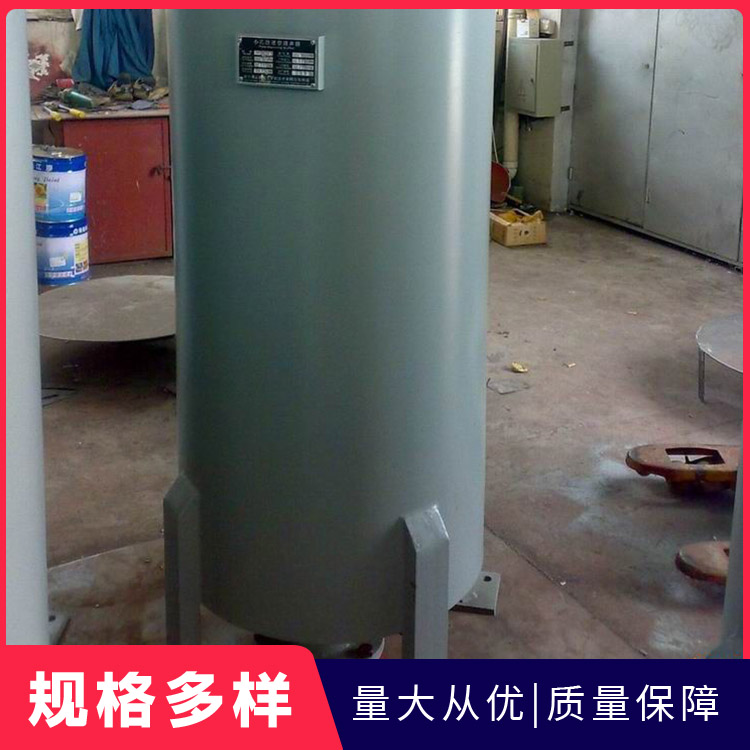
V. Product Images
1. Cooling Water Inlet 2. Cooling Tube 3. Shell Body 4. Main Body Flange 5. Cooling Medium Inlet 6. Vent Hole 7. Cooling Medium Sampling Port 8. Cooling Water Outlet 9. Installation Leg