

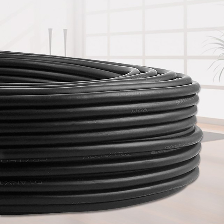


Roller Cable Coils

1. Scope This standard specifies the product classification, technical requirements, test methods, inspection rules, marking, packaging, transportation, and storage of drum-specific cables. This standard applies to drum-specific cables. 2. Normative References The provisions of the following documents are incorporated into this standard by reference. For dated references, any amendments (excluding corrections) or revisions to the referenced documents after the date of this standard do not apply to this standard, however, it is encouraged that the parties to this standard agree to use the latest versions of these documents. For undated references, the latest version applies to this standard. GB/T 3956-1997 Conductor of Cables GB/T 4910-1985 Tin-plated Round Copper Wire GB/T 3048.1-16-2008 Test Methods for Electrical Performance of Wires and Cables GB/T 3953-83 Round Copper Wire for Electrical Equipment GB/T 2951-1997 General Test Methods for Insulating and Sheathing Materials of Cables GB/T 4909.1-12-1985 Test Methods for Bare Wires GB/T 8170-1987 Rules for Rounding Numbers GB/T 7954.1-11-1987 Rubber Insulation and Sheathing for Wires and Cables GB/T 2952.1-3-1989 External Sheath of Cables GB/T 18380.1-2 Flame Test of Cables under Flame Conditions GB/T 12706.1-4-2008 Extruded Insulation Power Cables with Rated Voltage from 1KV (Um=1.2KV) to 35KV (Um=40.5KV) GB 5013.1-5-2008 Rubber Insulated Cables with Rated Voltage 450/750V and Below GB 6995.1-5-1986 Identification Marks for Wires and Cables GB 9330.1-2-2008 Plastic Insulated Control Cables JB/T 8137.1-4-1999 Delivery Reels for Wires and Cables 3. Product Naming and Codes 3.1 Codes
Company Code
Composite Mobile FF
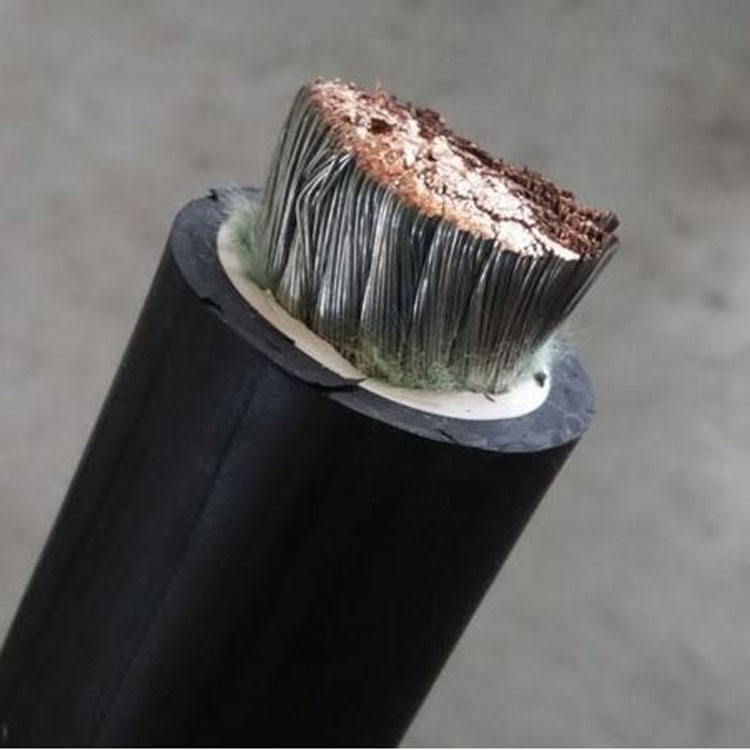
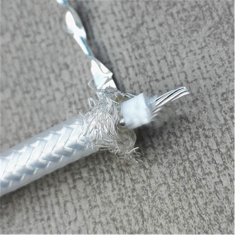
Silicone Rubber Insulation
Nitrile Sheath VF
Soft Structure R
3.2 Method of Expression 3.2.1 Products are represented by model number, specifications (rated voltage, number of cores, nominal cross-section) and standard number:
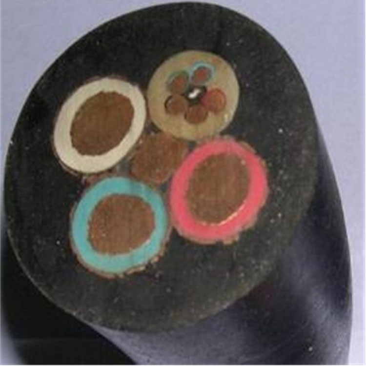
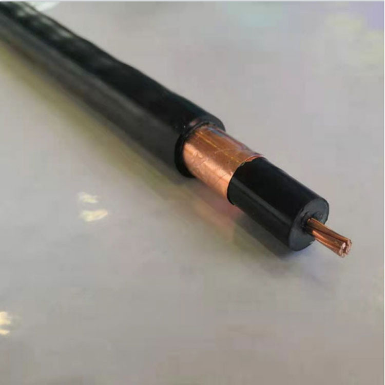
3.2.2 Example: Rated voltage 0.6/1KV, power wire core cross-section 16mm2, neutral wire core cross-section 10mm2, control wire core 9*2.5 mm2, represented as: GTFFVGR 3*16+1*10+9*2.5 0.3/1KV Q/JQ011-2008 4 Conductors 4.1 Conductors should be made of GB3953 TR-type soft round copper wire as specified in GB/T3956-1997. Copper single wires in the conductor cores may be tin-plated. 4.2 The conductor surface should be smooth, free of oil stains, and free from sharp edges, burrs, or damaged insulation, as well as protrusions or broken wires. 4.3 The conductor surface may be covered with an insulating layer made of suitable material. 5 Insulation 5.1 The average thickness of the insulation should not be less than the nominal value, and the thinnest part should not be less than 85% of the nominal value. 5.2 The insulation should be tightly bonded to the conductor surface, and there should be no visible bubbles, sand holes, or other defects in the cross-section of the insulation layer. Insulation should not be sticky between layers. 5.3 The insulated wire cores should withstand the spark test as specified in GB3048.9, as an intermediate inspection. The voltage for the spark test is listed in Table 1. Table 1 Spark Test Voltage
Insulation Nominal Thickness o mm AC Test Voltage kv Insulation Nominal Thickness o mm AC Test Voltage kv o ≤ 0.5 4 1.5 < o ≤ 2.0 15 0.5 < o ≤ 1.0 6 2.0 < o ≤ 2.5 20 1.0 < o ≤ 1.5 10 2.5 < o 25 5.4 For 5.4 Silicone rubber insulation, use the XJ-80 type as specified in GB7594.11, which should meet the requirements of GB7594.11. 5.5 The nominal thickness of the insulation for power core should comply with Table 2. The nominal thickness of the insulation for control core should comply with Table 3. 6 Cable Construction 6.1 The insulation cores of cables with two or more cores should be twisted together, with the direction being to the right. The construction gap should allow for filling, and the material should be a non-absorbent one compatible with the cable's operating temperature. 7.2 After construction, wrapping with an insulating tape is permitted, using a non-absorbent material compatible with the cable's operating temperature. 7.3 The lay length ratio of the insulated cable cores should be less than or equal to 8. 7 Sheath 7.1 The average thickness of the sheath should not be less than the nominal value, and the thickness at any point should not be less than 80% of the nominal value. 7.2 The sheath should be tightly extruded and should be easy to strip without damaging the insulation layer. 7.3 The surface of the sheath should be smooth, with even color, and the cross-section should be free of visible sand holes, impurities, and voids, with no defects affecting use. 7.4 The sheath should be made of nitrile plastic, with properties as specified in Table 4. 7.5 The nominal thickness of the outer sheath of the cable should comply with Table 2. The nominal thickness of the sheath for the control core should comply with Table 3. 8 Finished Cable 8.1 Conductor DC Resistance The conductor DC resistance should comply with the requirements of GB/T3956-1997. 8.2 Insulation Resistance The insulation resistance between conductor cores of the cable, when converted to 20°C, should meet the following specifications: 35 mm2 and below: Not less than 50 MΩ.km 50-150 mm2: Not less than 30 MΩ.km 185-240 mm2: Not less than 20 MΩ.km


