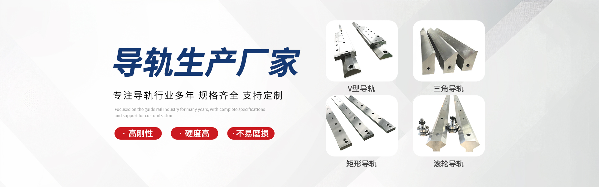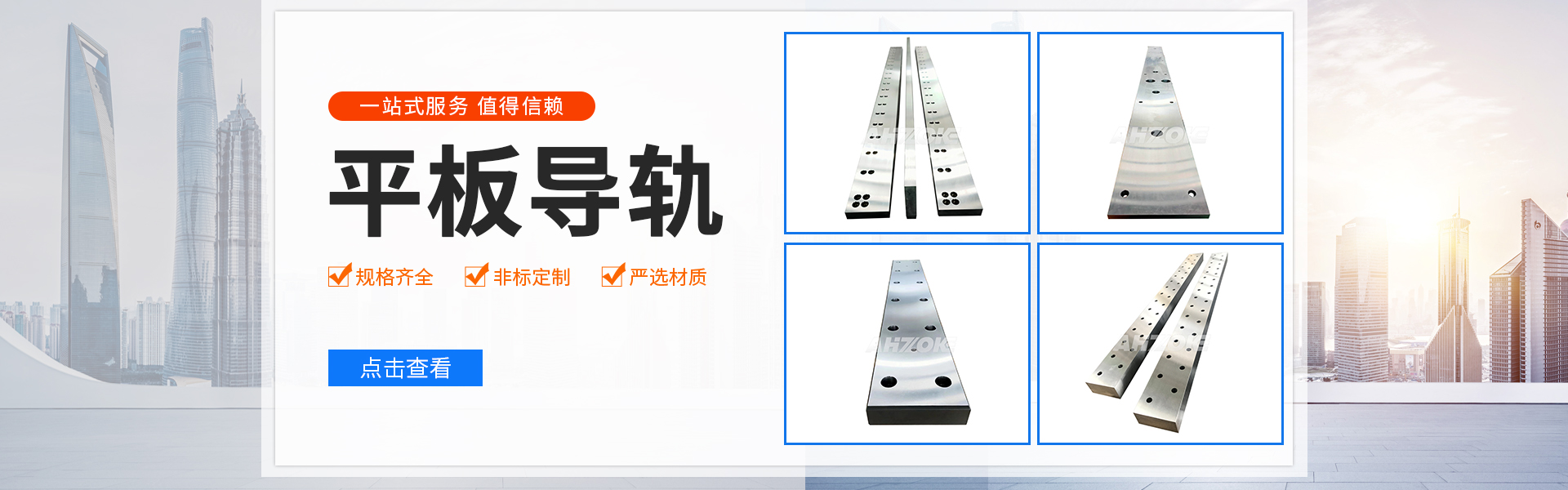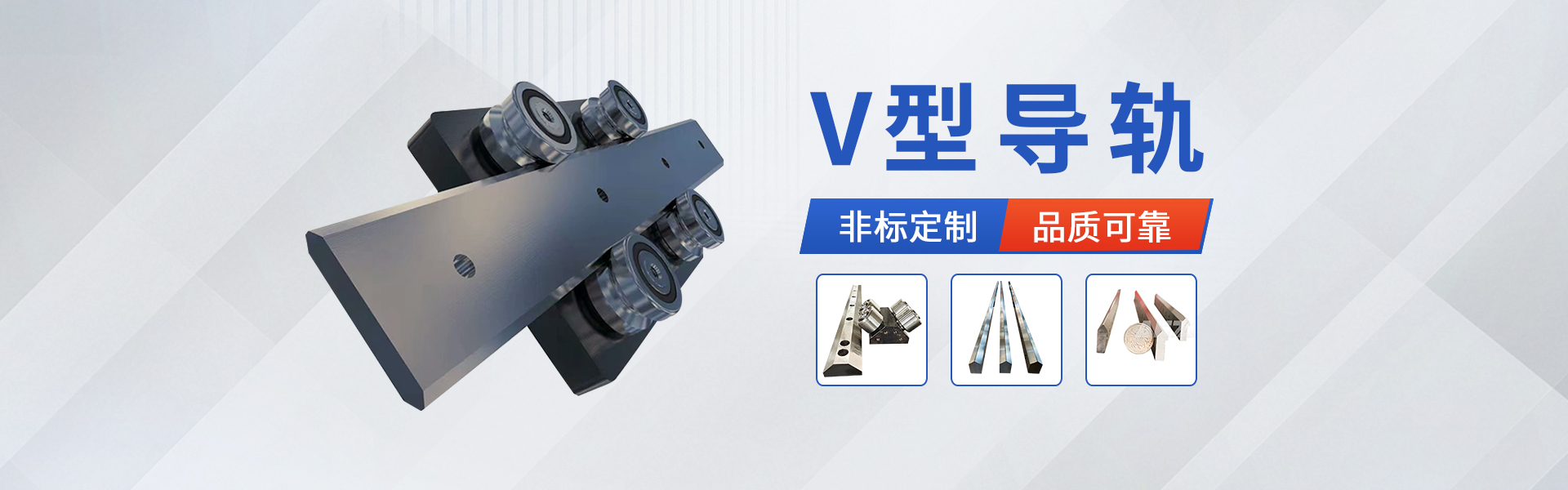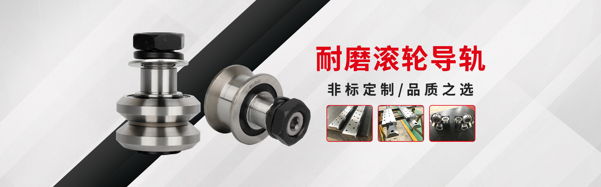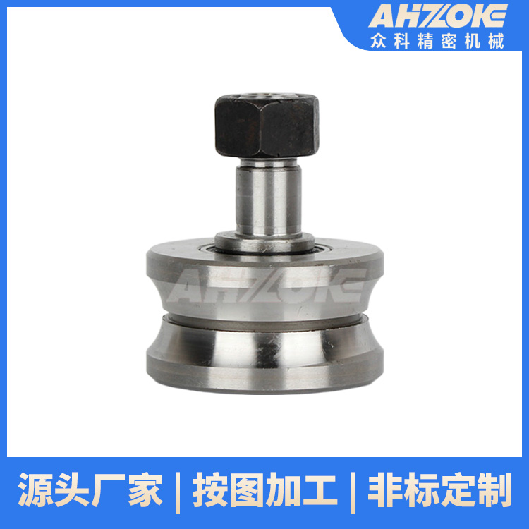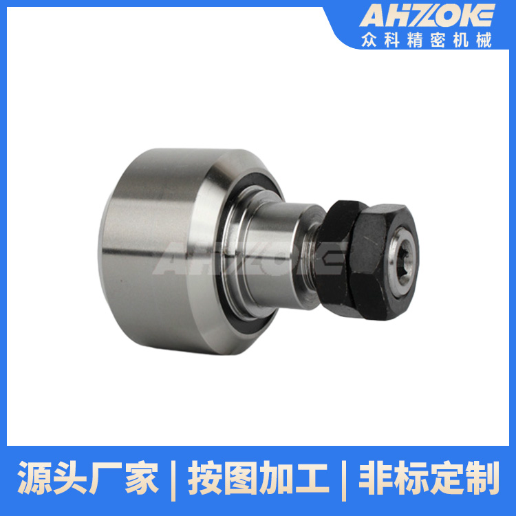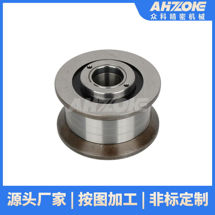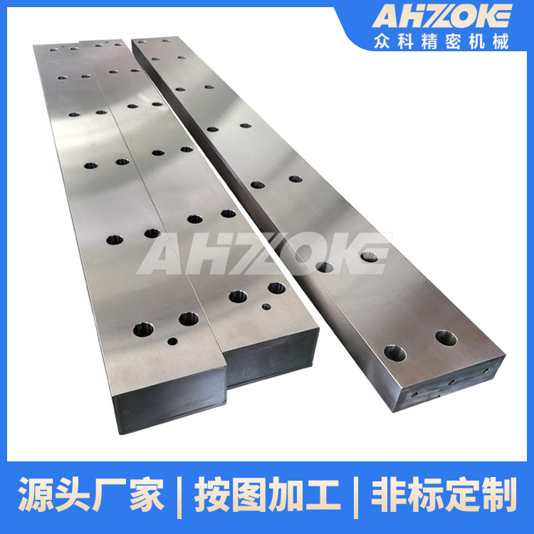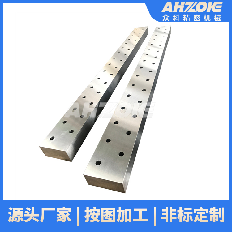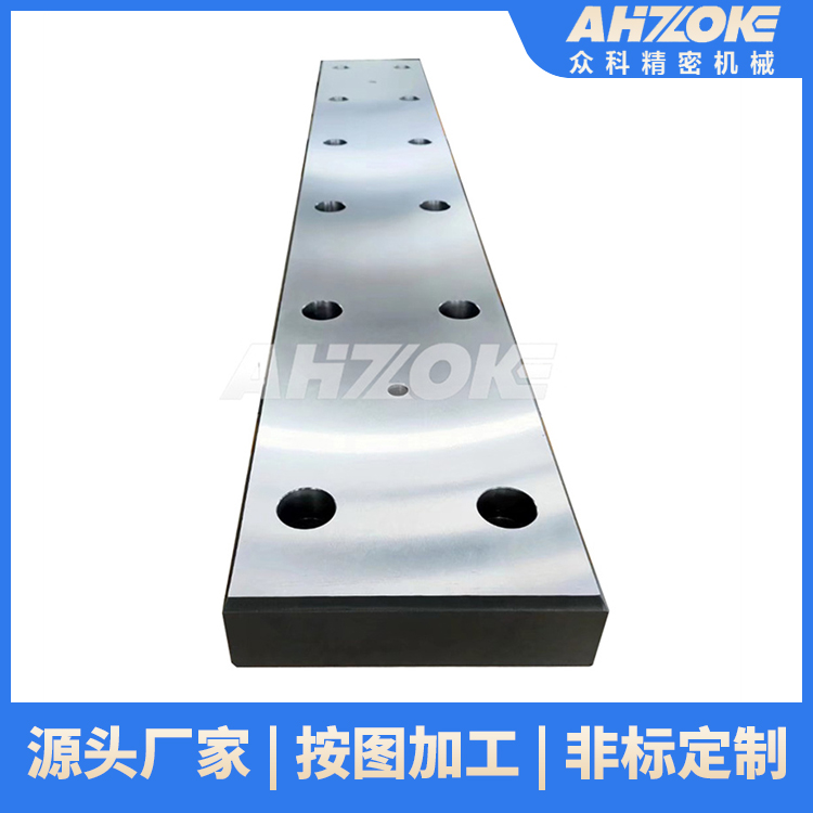
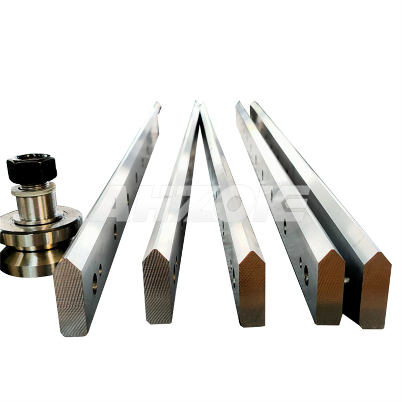
Rectangular guide ways, V-guide ways, machine tool guide ...

Installation errors in V-groove guides can affect the precision and stability of the equipment, thus requiring precise adjustments. Here are some common methods for adjusting V-groove guide installation errors:
Adjustment of Verticality Error
Inspection: Use a square or a verticality gauge to measure the verticality between the V-guide rail and the vertical reference plane. Align the reference edge of the square or gauge with the vertical reference plane, then touch the opposite edge to the surface of the V-guide rail. Read the verticality error value from the scale or indicator on the measuring instrument.
Adjustment: When verticality error occurs, first check if the mounting bracket of the guide rail is vertical. If the bracket is tilted, it needs to be corrected or replaced to ensure its verticality. For the verticality error of the V-shaped guide rail itself, it can be corrected by adjusting the installation angle of the rail. For example, loosen the installation bolt of the rail, use an angle adjustment tool (such as a wedge or an adjusting washer) to fine-tune the rail to achieve a vertical state, and then securely tighten the installation bolt.
Adjustment of Parallelism Error
Inspection: Typically, a dial indicator or a micrometer is used to measure the parallelism between the V-shaped guide rail and the relevant datum surface (such as the worktable surface or other guide rails). Secure the indicator stand on the datum surface, allowing the indicator tip to contact the V-shaped guide rail surface, then move the stand to different positions for measurements, acquiring parallelism error data.
Adjustment: If parallelism error exceeds the allowable range, first check if the installation bolts of the guide rail are loose. If so, tighten the bolts to the specified torque to ensure a secure installation. If the parallelism still does not meet the requirements after the bolts are tightened, add shims between the guide rail and the mounting surface for adjustment. According to the measurement results, add shims of the appropriate thickness to the areas requiring adjustment. Adjust the height of the guide rail by increasing or decreasing the number and thickness of the shims to achieve parallelism with the reference surface.
Adjustment of Straightness Error
Inspection: Utilizing laser interferometers or high-precision level gauges, measurements are taken along the length direction of the V-groove to determine the specifics of straightness error. For instance, measurements of the groove's height or level are taken at regular intervals (such as every 500mm), with the data recorded and a straightness curve of the groove plotted to visually understand the distribution of errors.
Adjustments: For minor straightness errors, adjustments can be made by modifying the support points of the guide rail. If there are local protrusions or depressions in the guide rail, the height of the corresponding support points can be appropriately adjusted to gradually restore the guide rail surface to a straight state. For larger errors, mechanical processing of the guide rail may be necessary, such as grinding or scraping, to remove high points or fill in low points, ensuring that the straightness of the guide rail meets the requirements.
Adjustment of Spacing Error
Inspection: For the spacing requirements between double V-groove guides or V-groove guides and other components, calipers, micrometers, or specialized spacing measuring tools can be used for measurement. Measure the spacing between guides or between guides and related components at different locations, record the measurement values, compare them with the required spacing in the design, and determine the spacing error.
Adjustment: If the spacing error is due to inaccurate installation position, it can be adjusted by moving the guide rail or related components. First, loosen the bolts securing the components, then move the parts to the correct position based on the measurement results, ensuring the spacing meets requirements, and finally, tighten the bolts to secure them. If the spacing error is caused by deformation of the guide rail or components, the deformed areas need to be repaired or replaced to restore the correct spacing.


b2b.china9.net © Zhongshang 114 Hebei Network Technology Co., Ltd.Address: Room 6009, Oriental New World Center, No.118 East Zhongshan Road, Qiaoxi District, Shijiazhuang City, Hebei ProvincePlatform Service Hotline: 4006299930