


1Product Selection Notice
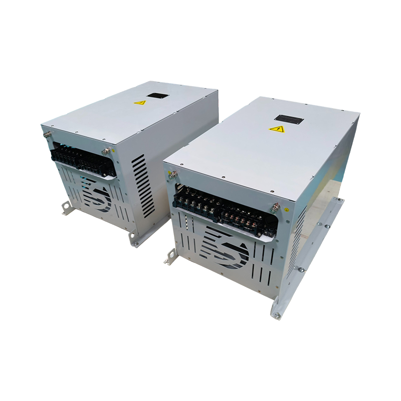
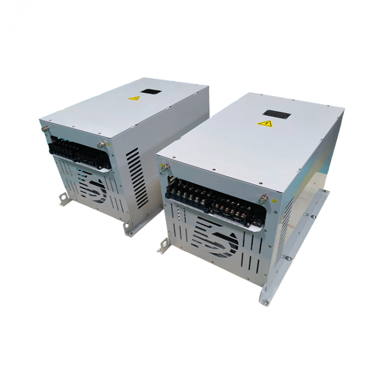
1、HFLIdeal for input to VFDs or other 6-pulse rectifiers, nearly eliminating harmonic distortion.
2HFL achieves superior THDI performance, enhancing energy efficiency, ensuring your system fully complies with harmonic standards (IEEE-519, EN61000-3-2, etc.).
3、HFLAll electrical installations and maintenanceThe work should be performed by a qualified electrical engineer.HFLThe connecting device must be grounded.
4、HFLAfter shutting off the power, wait for the intermediate circuit capacitors to discharge for 3 minutes.Before performing operations at different levels, please use a multimeter to confirm that the HFL input/output terminals have been fully discharged.
5When used with the load power, HFL can achieve good filtering effects. Larger power HFLs can be used for smaller load powers, but the filtering effect will be reduced.
6HFL can power multiple VFDs, but the total load must not exceed HFL's rated power capacity.
2Technical Data
Working Voltage | 380~415V | 480V | 690V |
Operating Frequency | 50Hz(±0.75Hz) | 60Hz(±0.75Hz) | 50Hz(±0.75Hz) |
Rated Power | 1.5~630kW | ||
Rated Current | ~1150A | ||
Harmonic Mitigation Capability THDI | HFL15: <15% / HFL10: <10% / HFL05: <5% / HFL03: <3% | ||
Efficiency | >98% @Rated power | ||
Maximum Voltage Rise Ratio | <6% @ No load | ||
Maximum Voltage Drop Ratio | <3% @ 100% load | ||
Overload Capacity | 120%IR for 3min per hour | ||
Temperature rise | ≤105k @Rated power | ||
Insulation Grade, Thermal Index | Class H (Reactor) | ||
IP grade | IP20 / IP00 | ||
Over-temperature Protection | 150 ℃ Normally closed (17AM150 AC250V 9A) | ||
Voltage Resistance Test | 3000 V AC50/60, 60s (lines/case) | ||
Insulation Impedance | DC1000V 100MΩ Min. (lines/case) | ||
Noise | <72dB | ||
Ambient Temperature | Operation Operation:-25℃~+45℃ (Refer to the Capacity Reduction Utilization Curve) Transportation Transportation:-25℃~+85℃ | ||
Humidity | 85%RH Max.No Condensation | ||
Highest Altitude | ≤1000m (No capacity reduction), >1000m (Refer to capacity reduction curve) | ||
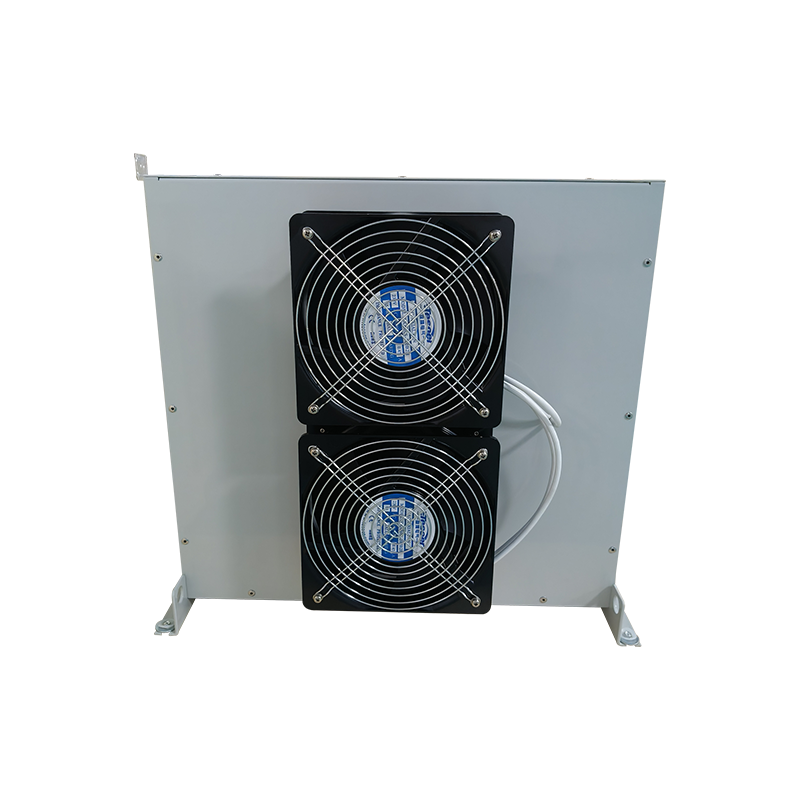
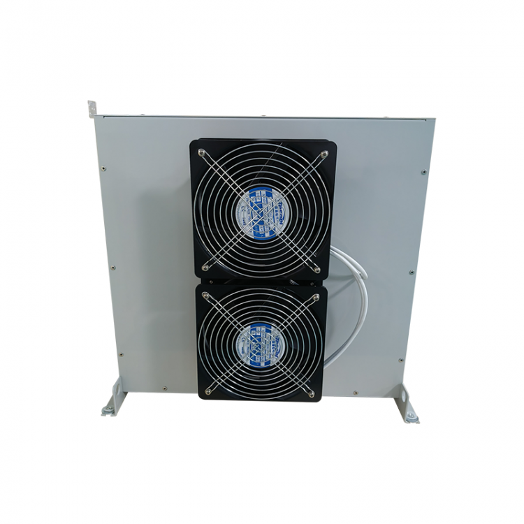
Cooling Method | Natural cooling,Fan cooling | ||
MTBF @ 45°C/400 V (Mil-HB-217F) | 200,000H | ||
Approvals & Compliance | CE (LVDWith EMC, RoHS, [Chokes: UL 1446, CAP: UL 810] | ||
Design Standardsnding to | Filter: UL 61800-5-1, EN 61800-5-1 / Chokes: EN 61558-2-20 or EN 60076-6 | ||
Comply with electrical power quality standards Meet power quality standard to | IEC/EN 61000-3-2 (GB 17625.1-2012), IEC/EN 61000-3-12 (GB/T 17625.x-200x) , IEC/EN 61000-3-4 (GB 17625.6-2003), IEC 61000-2-2/4 (GB/T 18039.3/4-2003) CE101 , IEEE 519 , G5/4 | ||
Note (remark): When the Total Harmonic Voltage Distortion (THVD) is below 2% (line voltage balance less than 1%) and the Short Circuit Power to Installed Load Ratio (RSCE) is greater than 66, the Full Load Current THDI of the VFD is reduced below the typical value at the HFL rated load. In cases where these conditions are not met or only partially met, harmonic reduction can still be significant, but it will not reach the rated THDI value. When the THVD of the supply voltage is less than 2%(line voltage balance is less than 1%) and the short-circuit power to installed load ratio (RSCE) is >66, the THDI of the supply current at full VFD is reduced to HFL Below the typical value at the rated load, in the case that these conditions are not met or only partially met, although the harmonics can still be significantly reduced, it will not reach the rating of THDI. | |||
3Electrical schematic diagram

4Typical performance curve
 THDILoad factor relationship curve
 Power Factor vs. Load Factor Curve
5HFL Current Waveform & FFT Analysis Comparison Before and After Use