


| Product Name | |
| Name Model | Aggregate Impact Tester
|
| 2. Sample Description | |
| This testing equipment is prohibited: Testing and Storage of Flammable, Explosive, and Volatile Substance Samples Testing and Storage of Corrosive Material Samples Testing or Storage of Biological Samples Fluid testing or storage | |
| 3. Equipment Features | |
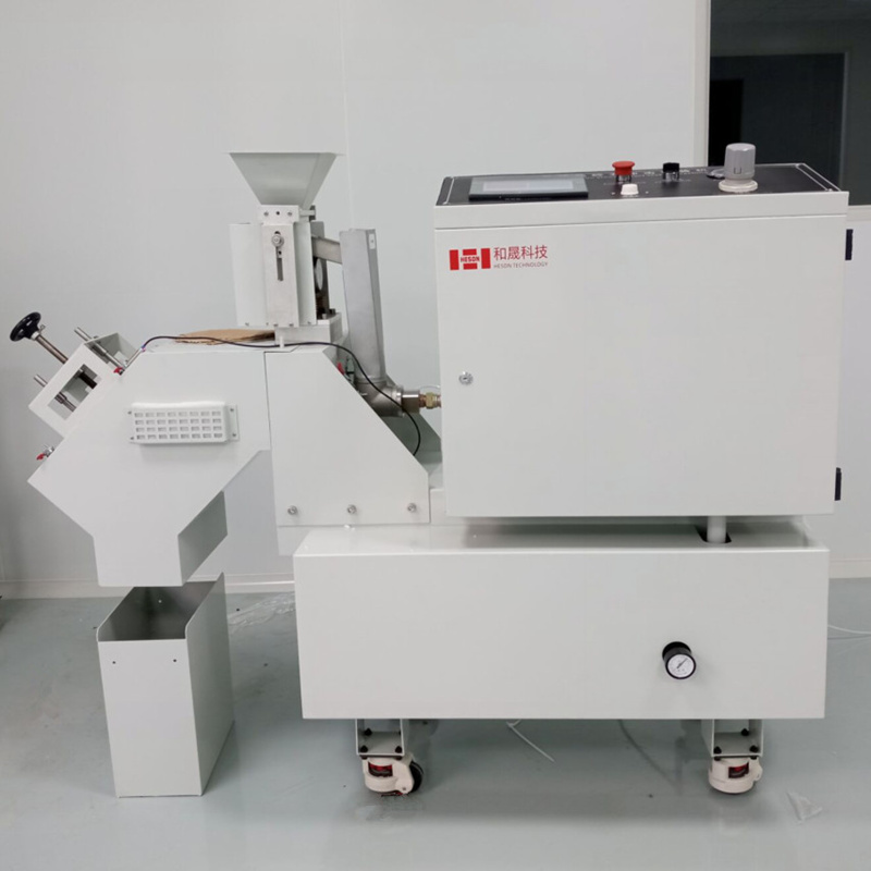
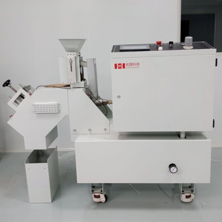
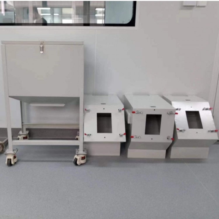
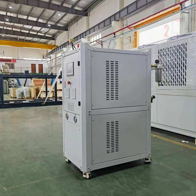
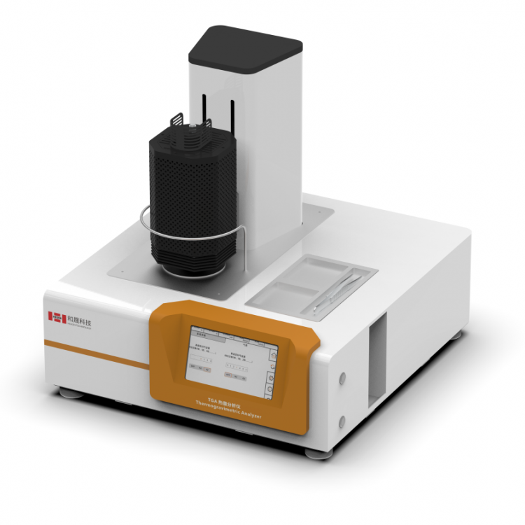
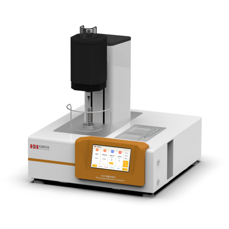
The equipment consists of: shooting gun assembly, collision housing, sample fixture, feeding funnel assembly (including a vibrator), electrical control system, and an air compressor (optional).
| |
| 4. Performance | |
| 4.1 Test Environment Conditions 4.2. Testing Standards Special Requirements | Ambient temperature: 5~35°C, relative humidity ≤ 85%RH Test box contains samples SAE J400 Automotive Surface Coatings Stone Chip Test ISO 20567-1 "Determination of Resistance of Coatings to Stone Impact -- Part 1: Multiple Impaction Test" DIN 55996-1:2001 "Test for Impact Strength of Coating Materials - Part 1: Multiple Impact Test" ASTM D3170-03(2007) GME 60268-96 GMW14700 GM9508P MGR ES30.AD.149 ISO 20567-1-2005 NES M0007 Section 28 DIN EN ISO20567-1-2007 FLTM BI 157-06 This feature specifies the protective ability of the coating to safeguard the axle from damage due to impact from projectiles, such as gravel roadbeds. This feature applies to Category 1. 4.1.4.2 Desired Characteristics Parameters After completing the tests as specified in 4.1.4.4, no holes should be found on the coating, and there should be no changes to the surface of the test specimen. 4.1.4.3 Sample for Testing The test sample should be a shaft or a local section of a shaft covered with the coating that requires evaluation. 4.1.4.4 Test Method Test specimens should be evaluated using the method of projecting particles onto the protected surface as outlined in Appendix C (Standard Edition). 4.1.5 Sanding Resistance 4.1.5.1 Overview This feature specifies the protective capability of the coating to protect the axle from damage due to repeated impacts of sand particles or flying sand. 4.1.5.2 Desired Characteristic Parameters After the test specified in Section 4.1.5.4 is conducted, the coating surface should comply with: For Category 1 and Category 2 protection, the coating loss grade is 3. For Category 3 protection, the coating loss grade is 4. As described in Appendix D (Standard Edition). 4.1.5.3 Sample Part for Testing The trial sample should be a shaft or a local section of a shaft covered with the coating to be evaluated. 4.1.5.4 Test Method The method for evaluating the resistance to sandblasting impact is provided in Appendix D (Standard Edition). Appendix C (Standard Edition) Evaluation Method for Impact Resistance of Coating C.1 Principle The testing method involves firing projectiles at the protected surface, followed by studying the changes in the coating and the surface of the test specimen. C.2 Test Sample Sheet The test sample should be a coated axle shaft or a coated protective part of an axle shaft that represents the finished product. C.3 Equipment This device is a machine capable of emitting processed projectiles (with a diameter of: 32mm, top angle of: 105°, and weight of: 60g). Its Vickers hardness should be 400. C.4 Program The air is ejected through expansion of a compressed air volume at 8 bars pressure to ensure an exit velocity of 19.4 m/s. Impact resistance is evaluated at -25°C and under ambient temperature conditions. C.5 Method of Expressing Test Results After impact, visually inspect the coating surface. Once the coating is removed, also inspect the exterior surface of the test specimen. Record and compare the surface changes according to the assessment criteria provided by this standard. |
| 4.3 Pressure Range | 0-1 MPa (Adjustable) |
| 4.4. Traffic Range | 0.0 to 0.08 m³/S (adjustable) |
| 4.5. Compressed Air Tube Inner Diameter | 12.7mm, 19mm or larger |
| 4.6. Air Slot Volume | 136L |
| 4.7. Bore diameter of the barrel | 52.6mm\290mm |
| 4.8. Maximum sample size | Width ≤ 105mm, Thickness ≤ 30mm |
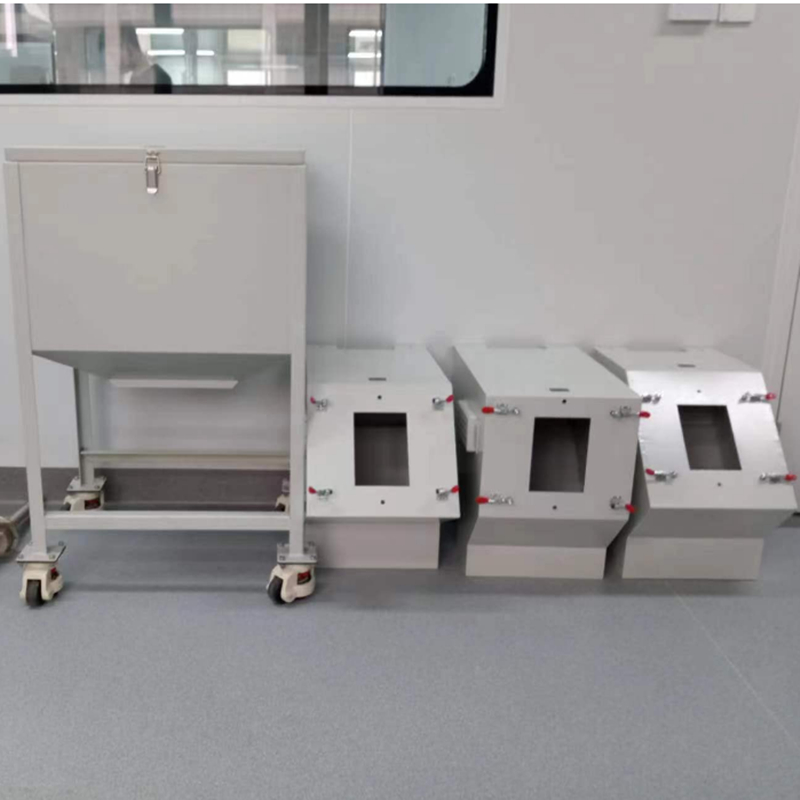
| 4.9. Collision Room and 3D Collision Room | SAE 45°-90°, VDA 54°-90°, Radiator collision chamber
|
| 4.10. Noise | ≦130dba |
| 4.11. Operation Method | Suitable for continuous operation |
| 4.12. Test Medium | Gravel, sand, steel grit (beads), iron grit (beads) |
| 4.13. Material Feed Rate | Adjustment through electromagnetic vibration feeder |
| 4.14. Airflow Pressure, Flow Rate | Internal storage compressed air, pressure and flow rate maintained constant, speed can be controlled by the adjustable valve at the nozzle. |