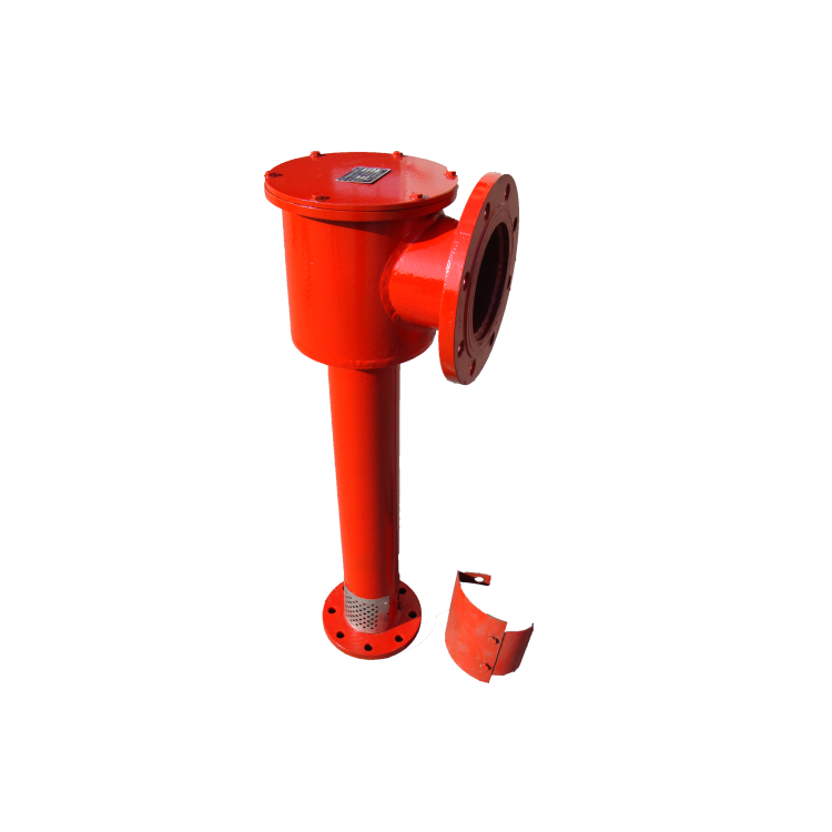


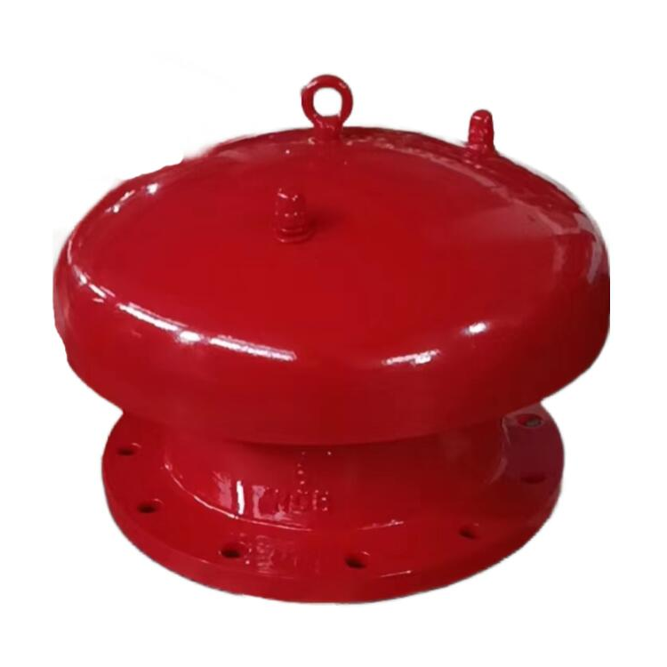
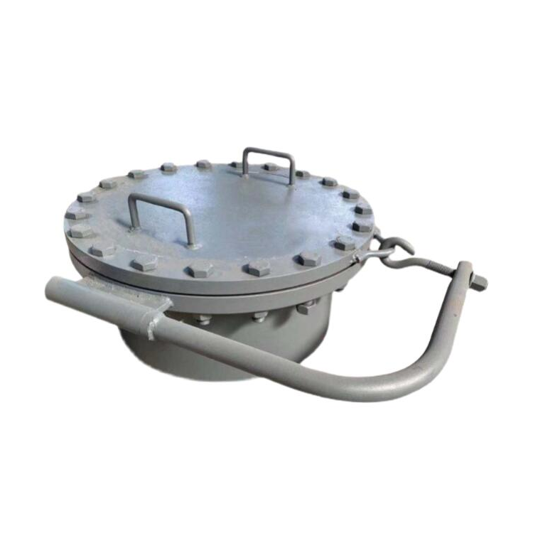
I. Product Introduction
The PCL type air foam generator is vertically mounted and fixed on the top wall of the oil tank, serving as a fire extinguishing accessory for producing and喷射ing air foam.
When the foam mixture supplied by a foam fire truck or fixed fire pump flows through the generator via the transport pipeline, it draws in a large amount of air foam, injecting the foam onto the burning liquid surface to form a foam layer or film. This is a key component of the low expansion foam fire suppression system.
Suited for independent Class A, B, C liquid storage areas and附属Class A, B, C liquid storage areas of enterprises with insufficient fire protection facilities.

II. Technical Specifications

Customers can select different rated flow values based on their usage needs, and each rated flow is equipped with a corresponding orifice plate.
Mixed Liquid Flow Rate Q: Q = K· ( Q:L/S、P:MPa)
The generator is suitable for use with: various types of foam liquids, 3% and 6%.
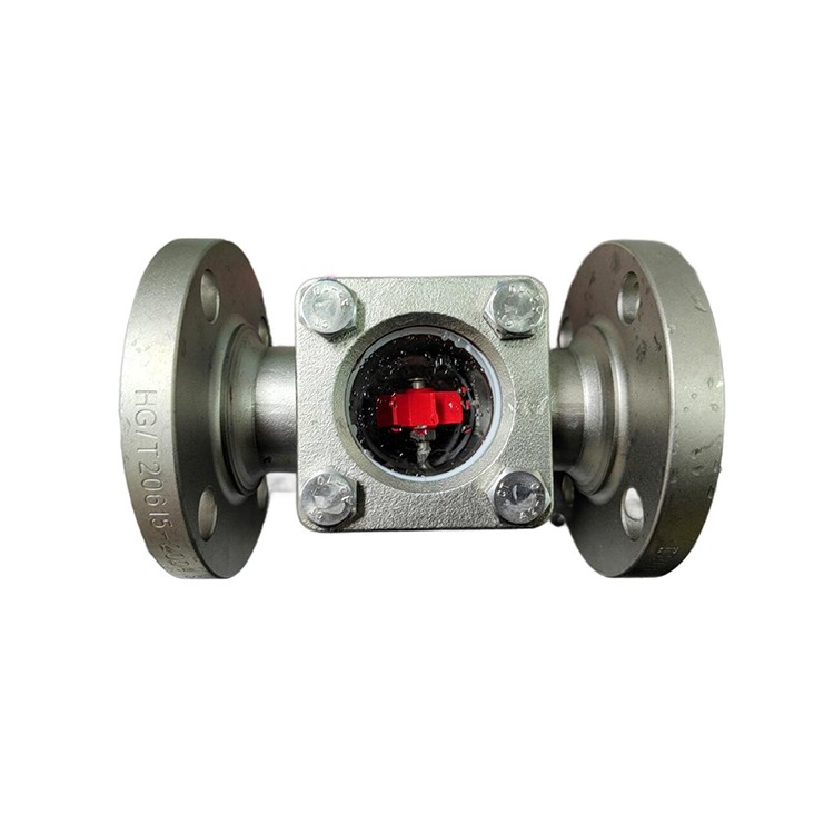
Section 3: Structural Principles
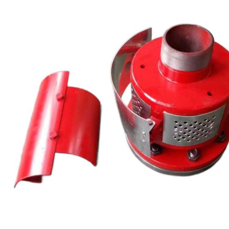
The PCL vertical foam generator is mainly composed of three parts: the housing assembly, the foam nozzle assembly, and the guide plate.
As the foam mixture flows through the nozzle of the generator, it forms a diffused atomized jet, creating a negative pressure around it that draws in a large amount of air to form an air-foam. The air-foam is then introduced into the storage tank through the foam nozzle and guide plates, flows down along the tank wall, and evenly covers the fuel surface to extinguish the fire.
4. Instructions for Use
1. The foam liquid generator's import calibration working pressure is 0.5MPa, and it can also be used within the pressure range of 0.3~0.5MPa, but the mixed liquid and foam liquid volumes will correspondingly change.
2. Fire pump water supply system, compatible with pressure-actuated air foam proportioning devices or pump-type proportioning mixers to deliver air foam mixture to the generator.
3. This product's unit is compatible with all types of foam liquids, including both 3% and 6% concentrations.
4. To prevent the evaporation of flammable liquid from the storage tank, a sealed glass must be installed at the shell outlet port. One side of the glass is etched with a fragile crack, which can be shattered at a mixture flow pressure of 0.1~0.2MPa. The side with the fragile crack should face the nozzle direction.
5. The deflector is installed on the inner wall of the storage tank, ensuring that the foam liquid flows down along the tank wall, uniformly covering the fuel surface to enhance the fire extinguishing effect.
V. Structural Dimensions

6. Installation
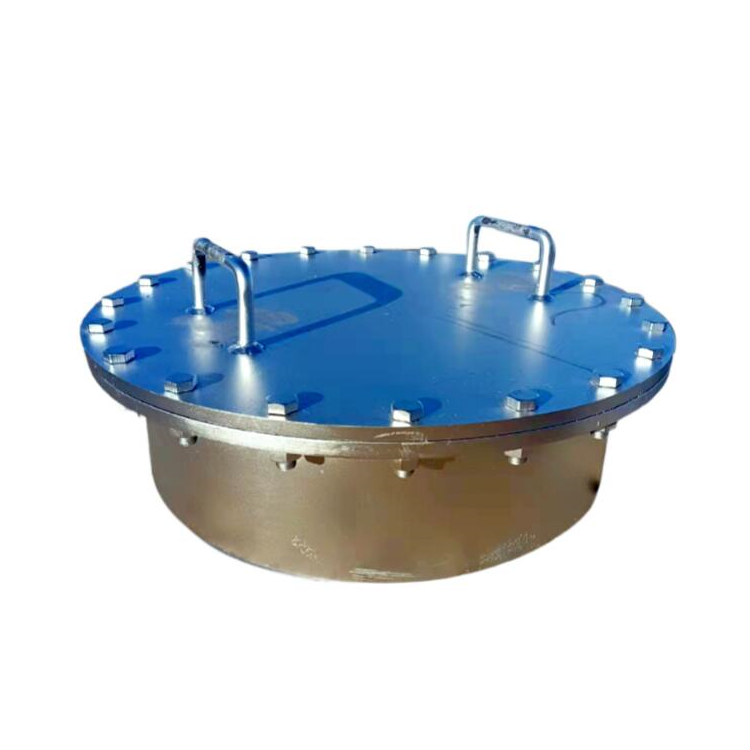
1. Vertical generator, installed vertically on the top of Class A, B, and C liquid storage tanks.
2. Generators should not be installed on the top of storage tanks. When used for external floating roof tanks, they should be mounted on the foam guide hood at the top of the tank.
When installing the generator, first make holes in the storage tank wall. Leave sufficient space at the top of the tank. The generator inlet should be elevated above the liquid storage level line of the tank by a certain dimension to avoid affecting the foam quality and formation, and to prevent liquid from flowing out of the generator opening. (See the dimensions shown in the outline dimension drawing for the hole size.)
Diameter and position of the opening on the drum, as well as the liquid level line and the top:


Section 7: Installation Precautions
1. If the generator is used to extinguish fires involving water-soluble Class A, B, or C liquids, the deflector assembly is not applicable and should be replaced with other suitable buffer devices (such as descent chutes, foam slides, etc.).
2. The nozzle of the generator must not be blocked by debris. Before the water spray test after the foam system is installed, the nozzle can be removed, and a metal plate can be used to cover the sealed glass area. Then, flush the pipeline, and after ensuring there is no debris inside, reattach the nozzle and proceed with the foam system tuning.
3. To prevent gas leakage from the generator within the storage tank, a sealed glass is installed at the outlet end of the generator housing. One side of the sealed glass has fragile scratch marks, which should face the outlet direction. The sealed glass will break upon being impacted by a 0.2MPa pressure mixture. The sealed glass should be installed after the foam system has been debugged. In case of damage to the sealed glass after each use or due to other reasons, it should be replaced promptly.
4. The generator can also be used to spray foam into the dike's containment area to extinguish fires flowing within. When installed outside the dike for use, it should be mounted on a plate that allows foam to flow to the surface of the burning liquid.
5. In cases where there are difficulties in sealing at the connection between the flange plane and the circular arc surface of the tank wall for a generator installed on the wall of a tank with a smaller diameter, it is advisable to increase the gasket or to weld the connecting flange directly onto the tank wall.
6. In special cases, the installation of generators should be based on the principle of not affecting the generator's performance. The diameter of the nozzle assembly can be slightly larger but not smaller, and the length can be slightly longer but not shorter. The guide plate assembly or other cushioning devices must be present, not absent. When replacing the guide plate assembly with other cushioning devices, the connection method to the storage tank wall should be specifically determined according to the structure of the cushioning device, and its requirements should meet the principles previously mentioned.
7. To ensure safety, a support frame should be placed under the generator. In the event of a fire, the storage tank may rupture or deform, potentially damaging the generator and pipes. To mitigate damage, install a metal flexible hose with shock-absorbing properties in the inlet pipe of the generator, or take other precautions.
Section 8: Installation Diagram