
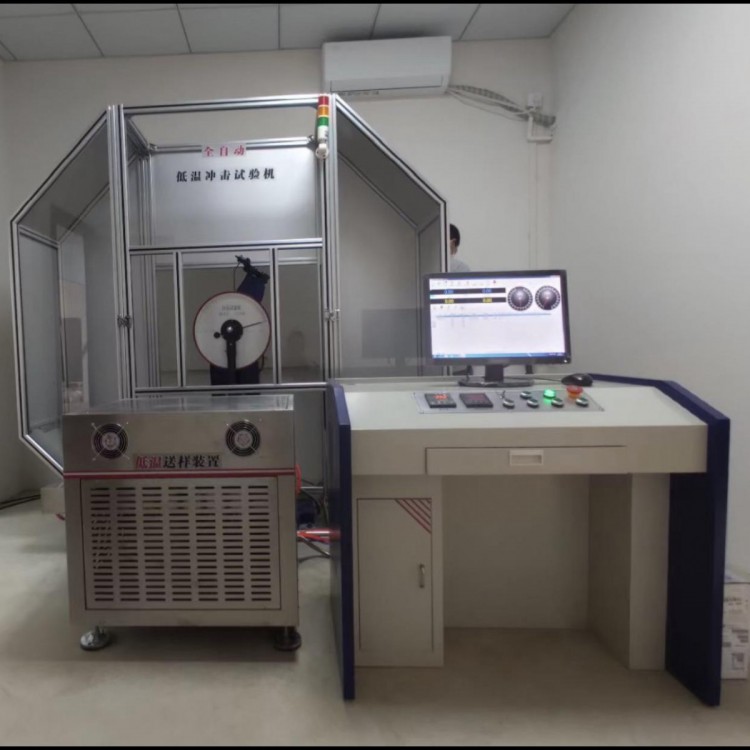


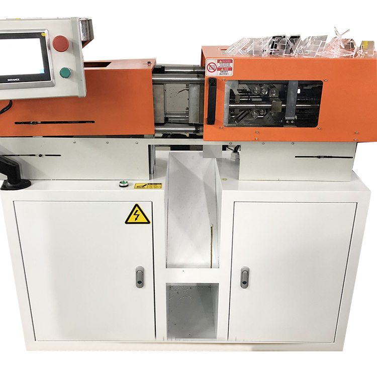

JBW-300BYⅡMicrocomputer-controlled low-temperature automatic impact tester


(Above is a semi-closed protective net as shown in the physical image, below is an aluminum alloy fully enclosed protective net.)
One. Equipment Name: Microcomputer-Controlled Fully-Automatic Low-Temperature Impact Tester
Model: JBW-300BYⅡ
Section 3: Performance Description:
JBW-300BYⅡ Low-Temperature Impact Tester, designed to test the metal materials' ability to withstand impact under dynamic loads. This model is a newly developed one by our company. Both the feeding mechanism and refrigeration unit are made of stainless steel, solving the issue of rust due to condensation on the shell caused by refrigeration, and the stainless steel material also offers an aesthetically pleasing appearance. The feeding mechanism features a newly designed high-precision rodless cylinder, addressing the problem of the old model where samples would freeze and not be fed out, or where the samples would jam. The new model boasts smooth sample feeding, quick cooling, and high temperature control accuracy. It serves as a testing instrument for metallurgical machinery manufacturing units and also as a testing instrument for scientific research units conducting new material research.
1. This machine is fully automated, with electrical and mechanical control for the swing, hanging, feeding, positioning, impact, and temperature regulation equipment. It is equipped with a dedicated feeding device for automatic feeding and automatic cross-section positioning of the sample. The time from the sample being taken out of the furnace to the impact is no more than 2 seconds, meeting the requirements of the low-temperature Charpy impact test method for metals. After the impact test, the remaining energy can be automatically used to swing the sample, preparing for the next test, ensuring high work efficiency.
2. The main structure of the testing machine is split-type, with cantilever suspension method and U-shaped pendulum hammer body.
3. The impact blade is fixed with screws for easy replacement.
4. Simply supported beam specimen support
5. The main unit is equipped with a safety guard; an all-enclosed aluminum alloy guard is also available as an option.
6. The testing machine conforms to the national standard GB/T3803-2002 "Inspection of pendulum impact testing machines" and performs impact tests on metal materials in accordance with the national standard GB/T229-2007 "Impact test method for metallic夏比notched specimens".
IV. Main Technical Specifications:
1. Impulse Energy: 150J, 300J
2. Pendulum Torque (Impact Constant): 300J: 160.7695 N·m
150J:80.3848N·m
3. Swing pendulum pre-tilt angle: 150°
4. Distance from center of shaft to impact point: 750mm
5. Impulse Speed: 5.24 m/s
6. Sample Support Span: 40mm
7. Clamp Mouth Radius: R1-1.5mm
8. Impact Blade Edge Radius: GB R2-2.5mm, ANSI R8
9. Impact Blade Thickness: 16mm
10. Impact blade angle: 30° ±1°
11. Refrigeration Method: Compressor Cooling
12. Heating Unit: Plate Heater
13. Sample Box Capacity: Not less than 20 units
14. Low Temperature Range: 40 to -85℃
15. Temperature Control Accuracy: ±0.5℃
16. Sampling Rate: 0.01s/s
17. Angular Resolution: 0.001° - Any angle can be set
18. Sample Size: 10 (7.5, 5, 2.5) × 10 × 55mm
29. Dimensions: 1500 mm x 850 mm x 1340 mm
20. Net Weight of Testing Machine: 850 Kg
21. Power Supply: AC 3-phase 380V±10% 50Hz 5A
22. Environmental Conditions: No corrosive medium, no vibration, no strong electromagnetic field.
23. Environmental Temperature: 10-35℃
V. Main Equipment Configuration:
One 300 joule main unit.
2. A 150J and a 300J pendulum each
One motor (mounted on the main unit).
4. A set of pendulum drive assembly (mounted on the main unit)
5. A set of automatic hanging device (mounted on the main unit)
A set of refrigeration temperature control equipment.
7. A set of automatic feeding device (mounted on the main unit).
A set of safety protection devices.
9. One pedestal adjuster.
10. Sample Aligner Unit (1 pc.)
11. One disassembler (for replacement use)
One proximity switch;
13. A set of dedicated control and measurement software
14. A complete set of Lenovo desktop computers
One printer
16. Foot screws, 4 pcs
17. Adjust three wedge irons
Section 6: Mainframe Structure and Operating Principle:
The Low-Temperature Impact Tester consists of the main unit, low-temperature device, feeding mechanism, and automatic positioning mechanism.
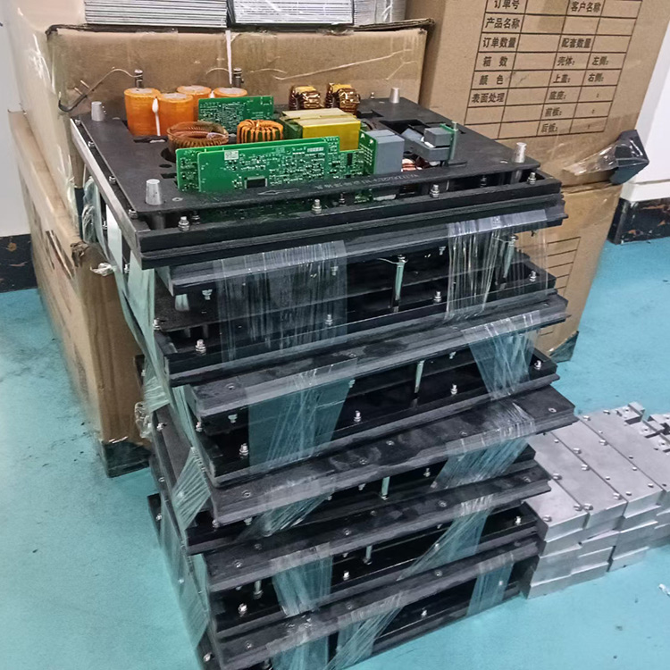
Low Temperature Equipment: This low temperature equipment is our company's newly developed refrigeration system, designed in accordance with the requirements of GB/T229-2007 "Method for Impact Test of Metal by Charpy Hammer," specifically for low temperature devices. It employs a cascade refrigeration technology with a compound compressor, utilizing the principle of thermal equilibrium and cyclic mixing to achieve automatic, uniform cooling and constant temperature of the specimens, meeting all the temperature control standards specified by national standards. The low temperature tank is controlled by a single-chip microcomputer, featuring digital temperature display, automatic temperature control, automatic timing, and automatic alarm, ensuring simple and safe operation. It has fast refrigeration speed, large capacity, and high temperature control accuracy, making it an ideal cooling and insulation equipment for low temperature impact tests on metal materials.
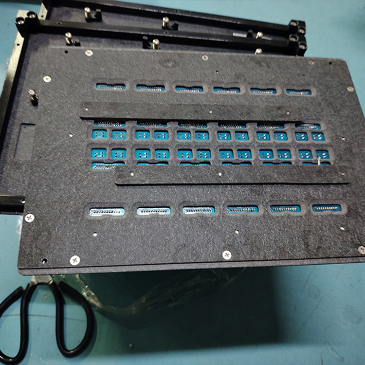
Feeding Mechanism: After the sample is cooled to the set temperature in the low-temperature device, the feeding mechanism can quickly and reliably deliver the sample to the clamp support surface. The pneumatic feeding mechanism consists mainly of two parts: the cylinder and the feeding device. The movement of the feeding mechanism is a straight-line motion, driven by compressed air entering the cylinder to push the piston, which in turn drives the feeding rod to advance and feed quickly and then reset. The advancement, retraction, and stopping of the feeding rod are controlled by the pneumatic directional valve of the feeding cylinder and the magnetic switch, which emit electrical signals to control the cylinder's advancement and retraction. Adjusting the position of the magnetic switch allows for fine-tuning of the feeding rod's position and buffer speed.
Locating Mechanism: The specimen must be tightly adhered to the side of the clamp mouth, ensuring the specimen notch is precisely centered along the pendulum axis. The tight adherence to the clamp side is guaranteed by the locating mechanism. As the specimen is fed to the front support by the feeding rod, due to the action of the fixed spring plate, it moves forward tightly against the clamp side. When the rear end of the specimen has not yet detached from the fixed spring plate and the front end enters the back clamp face, the collision plate in the feeding mechanism triggers a signal, causing the electromagnet to activate. Subsequently, the locating mechanism engages, the locating rod reaches the working position, and the side elastic stopper of the locating mechanism presses the specimen tightly until the front end of the specimen adheres to the locating surface, completing the specimen locating process. When the feeding rod spring is compressed (22mm to 3mm), the electromagnet receives a signal again and resets, moving the locating mechanism away from the specimen and the locating surface to allow for impact. The locating mechanism is integrated with the bracket; the electromagnet's pull and the spring's reset move the locating block up and down, pushing the locating screw against the spring, ensuring the screw remains tightly against the locating surface. Simultaneously, through a pin on the sliding sleeve, the locating mechanism rotates the side elastic stopper. The eccentric block reduces the inertial impact of the locating mechanism on the specimen, thereby enhancing the accuracy of the specimen locating.
Section 7: Safety Protection Introduction
At the initial design stage of the testing machine, we have fully considered the safety of the equipment during operation and have implemented the following protective measures:
Firstly, the fully enclosed protective hood ensures that the enclosed space within the hood is used for testing, preventing the sample from "flying out" and causing injury.
Next, when the test personnel open the left or right hood to enter the machine's interior, the control system will lock the machine, preventing any operation, thus ensuring the safety of the test personnel.
The cylinder for centering devices features a detection switch, allowing disengagement of the oscillating impact only when the cylinder is reset, ensuring the safety of the centering device.
The equipment is also designed with multiple protective devices to ensure safe and reliable operation.
1) Set Position Limit Protection
2) Safety Door Chain Protection
3) Door access locks for left and right side covers
4) Interlock protection between the operation panel and the supervisory control software interface
5) Brake Wear Protection
6) Immediate braking protection upon power failure
7) Full-enclosed protective hood is provided; fractured specimens are automatically sent out by the fractured sample recovery device.
8) The safety door interlock system is in place, ensuring the safety of personnel.
9) Interlock protection between the operation panel and the supervisory software interface, preventing erroneous operation
10) Featuring a safety warning light and a liquid crystal display that can show all abnormal conditions in real time.
Section 8: Introduction to Measurement and Control Software

Main Interface
One, toolbar

Figure 2.2
Including ten sections: New, Open, Save, System Parameters, Export to Word, Export to Excel, Cycle Measurement, Pointer Friction, System Error, Exit.
1. New
Feature:
Input of sample data allows for adjusting the number of samples per group, and customizing items as needed.
Method:
Click![]() Buttons, input test data. After entering width and thickness, the area is automatically calculated, as shown in Figure 2.3:
Buttons, input test data. After entering width and thickness, the area is automatically calculated, as shown in Figure 2.3:

Figure 2.3
l Change the number of samples
Click![]() Plus and minus signs on both sides of the button allow for adjusting the number of samples.
Plus and minus signs on both sides of the button allow for adjusting the number of samples.
l Customized
Click![]() Enter password 123456, click Confirm, a window similar to Figure 2.4 will appear:
Enter password 123456, click Confirm, a window similar to Figure 2.4 will appear:

Figure 2.4
Below the display name, there are "Custom 3, Custom 4," etc., simply click to enter the desired item name for customization.
l Data Name Displayed
After customizing the required items, if you need them to be displayed in the software, change the corresponding "Display" column data to 1; for data names that should not be displayed, change the corresponding "Display" column data to 0.
Adjust parameters, then click "OK" to save; unless there's a specific need, please do not modify any predefined items arbitrarily.
2. Open
Feature:
Locate test records based on the test date, batch number, and operator.
Method:
Click![]() Button
Button
In the year, month, and day dropdown menus, select the test date you wish to find, click 'Search Test Records', and confirm to view.
3. Preserve
Features:
After manually altering data, proceed to save.
Description:
Upon completion of the test, the test data is automatically saved.
4. System Parameters
Function:
Custom software parameters.
Description:
Do not alter the customized parameters unless there are special requirements.
Method:
Click the toolbar![]() Button, confirm to enter system parameter settings, as shown in Figure 2.6:
Button, confirm to enter system parameter settings, as shown in Figure 2.6:

Figure 2.6
1) Maximum range, the maximum impact energy of the impact testing machine.
2) Encoder Resolution, i.e., the encoder's line count.
3) Initial angle, the angle when the pendulum is raised to its maximum inclination.
4) Fullness Adjustment, Correction of the Fullness Angle
5) Minor pendulum adjustment; correction of pendulum angle
6) Large swing zero-point correction, energy adjustment for large swing during empty impact
7) Minor adjustment for small pendulum's energy correction during air impact
8) Adjust the large swing pre-elevation angle; correct the large swing pre-elevation angle.
9) Adjust the preliminary pitch angle of the small pendulum; correct the preliminary pitch angle.
10) Language, available in Simplified Chinese and English.
11) Versions include manual feeding, electric feeding, and pneumatic feeding.
12) Energy accuracy, the decimal places of energy value display;
13) Angular accuracy, decimal places of angle value display
14) PLC parameters, identical to the functions of the software parameters listed above.
15) Host parameters, calculated values determined by periodic measurement.
5. Output Reports
Features:
Print out the test report in both Word and Excel formats.
Description:
This feature requires the installation of Word and Excel programs on the computer.
Method:
Click![]() Button:
Button:
Automatically pop up test reports, which can be modified individually for each data; report styles can be freely edited; simply click "File" and select "Print" to print the Word format report.
Click![]() Button:
Button:
Pop up to select printing Excel format reports. Report styles can be freely edited.
Two, Indicating Display Section

Figure 2.7
1、Angle
Feature:
At the start of the test, click to initiate, the angle display bar will show the angle value of the pendulum lifting until the limit angle; after the impact is complete, during the pendulum's descent, the angle will be displayed until it returns to zero.
Method:
Range![]() Select button; use the large pendulum for the 300J range; use the small pendulum for the 150J selection.
Select button; use the large pendulum for the 300J range; use the small pendulum for the 150J selection.
![]() Zeroing Angle Button; The pendulum can be zeroed when it is in its natural state, not in any other state.
Zeroing Angle Button; The pendulum can be zeroed when it is in its natural state, not in any other state.
2. Energy
Feature:
Display the impact energy value generated after the impact.
Section 3: Results Display Panel

Image2.8
1. Impulse Energy
Feature:
Display the maximum impact energy value after the test is completed.
2. Impact toughness
Feature:
Display the impact toughness value after the test is completed.
Four: Simulated Dial

Figure 2.9
1. Angle Display Panel
Feature:
The angle display board shows the pendulum angle, with the blue pointer indicating the actual value and the yellow pointer indicating the peak value.
2. Energy Display Panel
Features:
The energy display board shows real-time energy, with the blue pointer indicating the actual value and the yellow pointer indicating the peak value.
Five: ControlPanel

Figure 2.10
1. Hem
Function:
Lift the pendulum to its maximum tilt angle.
2. Material Supply
Feature:
If an automatic feeding device is available, simply click to complete the sample feeding.
3. Returns & Resales
Function:
After material delivery is complete, click to retract and release the safety pin.
4. Impact
Features:
Click on the impact fracture specimen.
5. Drop Hem
Feature:
After the test is complete, click the pendulum button, and the pendulum returns to its natural state.
Section VI: Record and Statistics Area

Figure 2.11
Feature:
Display test results data, including impact energy and impact toughness, etc.
Section 7: Record Operation Area
![]()
Figure 2.12
Feature:
Review and modification of test results, as shown in Table 2.1:
| Select a test data item: Click the button to automatically jump to the first test data item |
| Select the last test data entry: Click the button to automatically jump to the last test data entry. |
| Select previous data entry: Click the button to jump to the previous test data record for the current experiment |
| Select Next Data Record: Click the button to navigate to the next test data in the current test record. |
| Add Test Data: Click the button to automatically add test data of the same specification |
| Delete Test Data: Select the test records to be deleted, click the button, and delete the selected data |
| Revise Test Data: Select the test record to be revised, click the button, and you can modify the test data. |
| Save Test Data: After modifications are complete, click the button to save the updated test data. |