


Magnetic Flip Level Gauge
I. Structural Features:
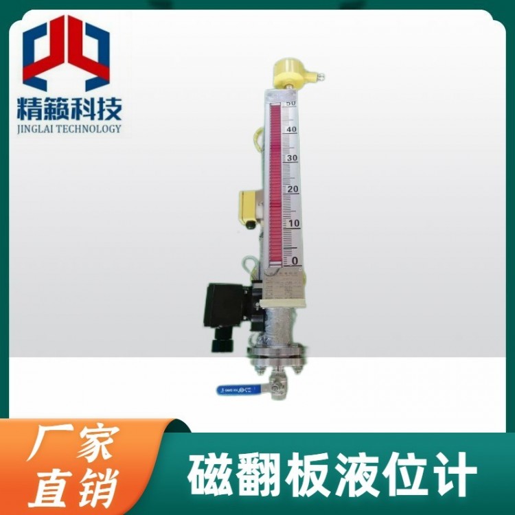
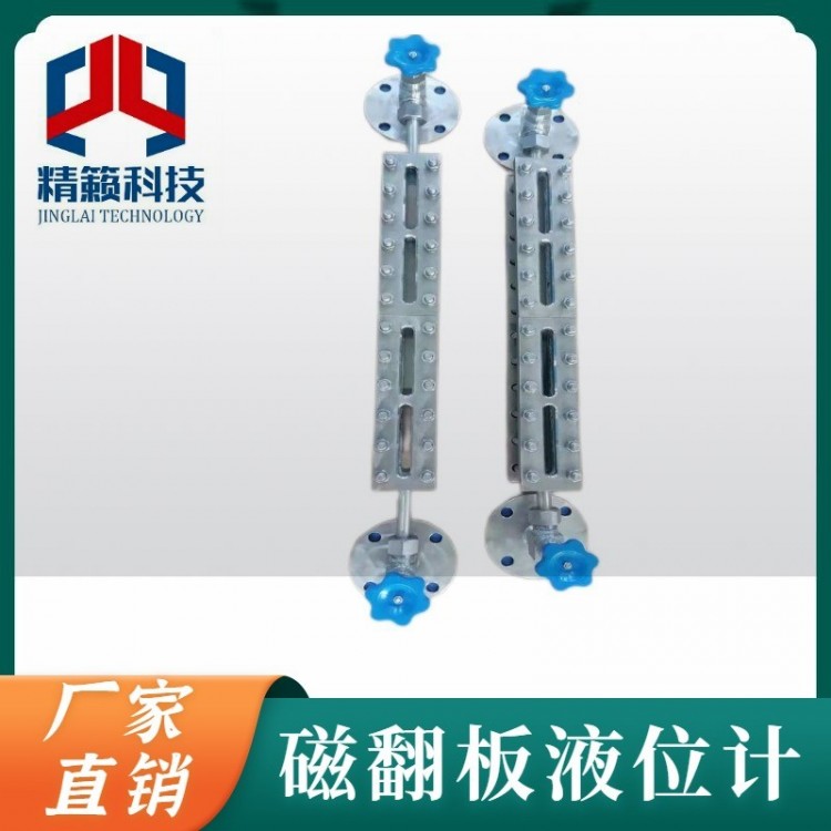
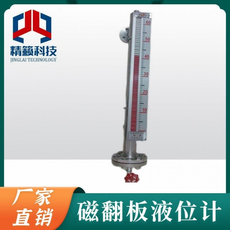
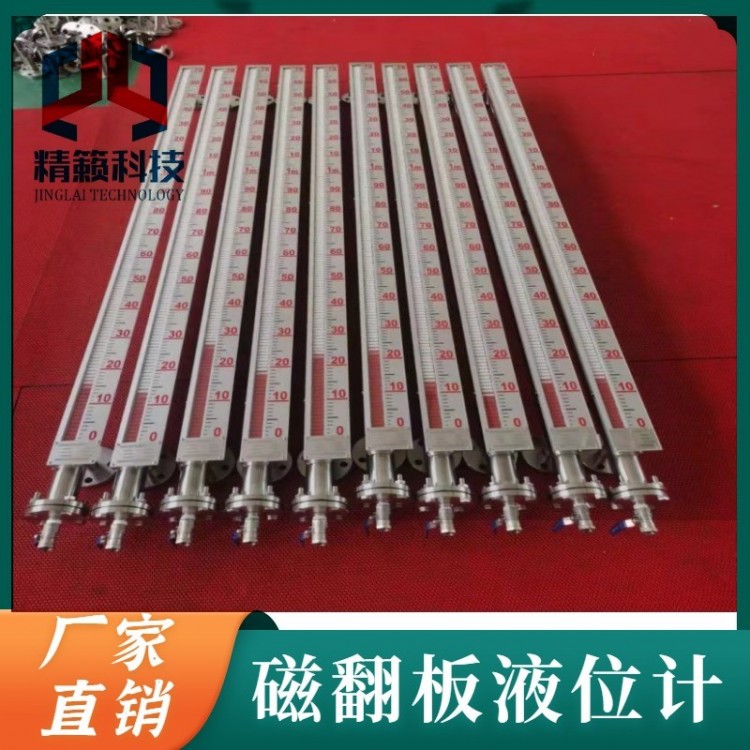
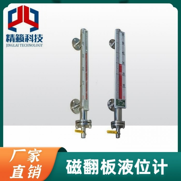
Basic Level Gauge operates based on the principle of buoyancy. The float moves up and down within the measuring tube with the liquid level. The magnetic steel inside the float drives the red and white pointer to flip 180 degrees through magnetic coupling. As the liquid level rises, the pointer changes from white to red, and when it falls, it changes from red to white, indicating the liquid level accordingly.
Limit switch output utilizes a magnetic float to move with the liquid level, causing the spring switch mounted at the set position of the level gauge's vertical tube to activate, achieving ON-OFF control or alarm.
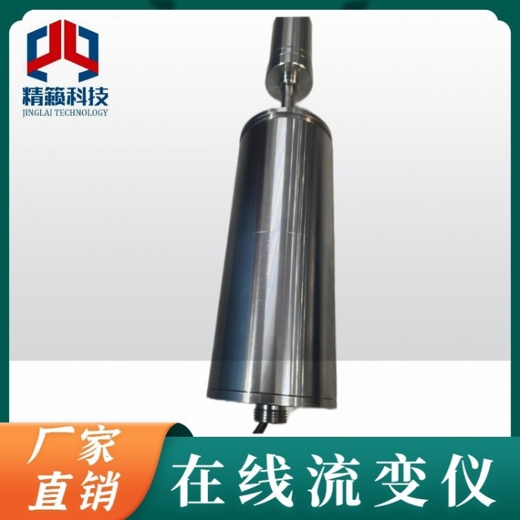
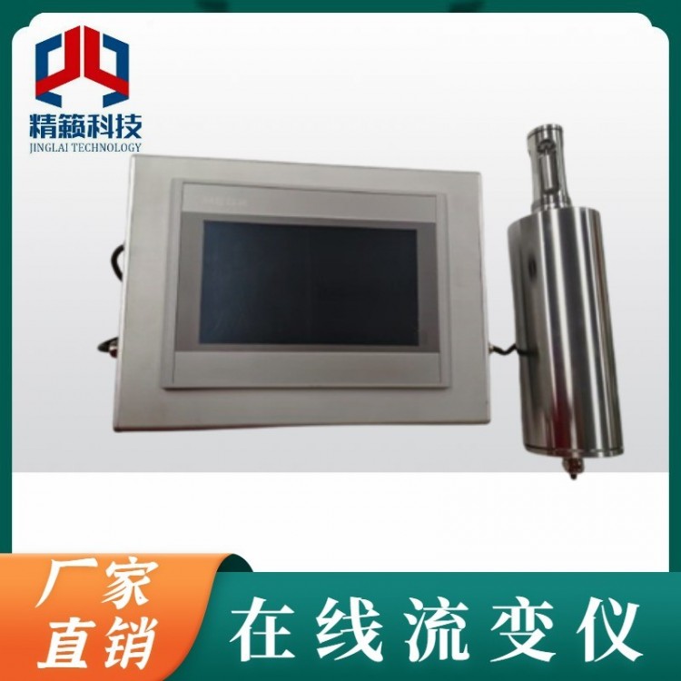
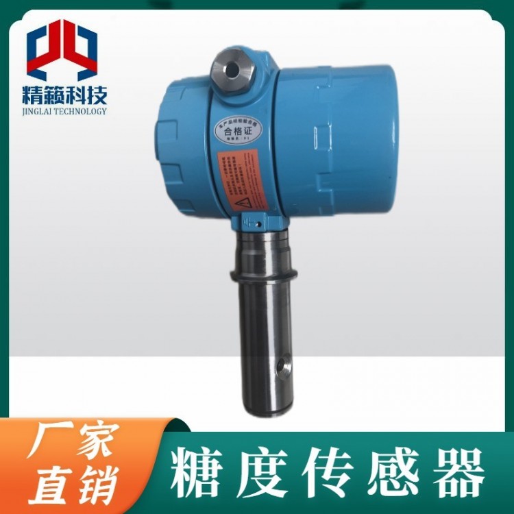
Transmitter installed on an electromagnetic float level gauge. The transmitter consists of a sensor and a converter, which, through the up and down movement of the electromagnetic float, sequentially actuates the measuring components inside the tube via magnetic coupling. It then obtains a change in resistance signal, which is converted into a standard current signal of 0~10mA or 4~20mA for output. This allows for connection with digital display meters or computers, enabling remote display.
II. Working Principle:
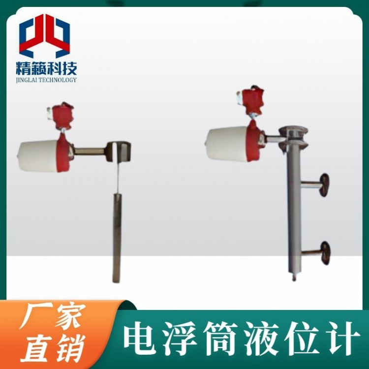
This product consists of the main body, a flip-top box (comprising red and white magnetic flip-top switches), a float, a flange cover, and a level transmitter, as shown in the diagram. The working principle is as follows: The flip-top box and transmitter outside the main body are actuated by the float inside (equipped with directional magnetic sources, specifically designed for different media and pressures), causing the flip-top to flip and display red and white colors, indicating different liquid surface heights as the float moves. Simultaneously, the level transmitter transmits the liquid level signal to the control center for level indication and control. It can also be centrally monitored via computer.
Section 3: Main Technical Specifications:

Model No.
The composition of the magnetic float level gauge with tilting column is as follows:


2. Model Marking Example:
UFYZ-34-1111, L=2500, ρ=0.6, Side-mounted, ABS (0.6MPa), Basic Model, Installation Spacing 2500mm, Medium Density 0.6g/cm³.
UFYZ-34-2232 □ L=2500 L1=3000 ρ=0.5 Top-mounted, Stainless Steel (2.5MPa), with Upper and Lower Limit Switch Outputs, Measuring Range 2500mm. Installation Depth 3000mm, Medium Density 0.5g/cm³.
Ordering Instructions:
Please specify the model specifications, measurement range, installation depth, medium density, medium temperature, and working pressure when placing an order.
If you're using flanges in JB, HG specifications, or other types, please specify. Our factory professionals will assist you in selecting the right type or design and manufacture special products for you.
Customers must provide their own flanges and gaskets, etc., as listed in the table below. The relevant dimensions of the flanges provided by the customer, as well as the sealing dimensions, can be found in the image and table below:

V. Extendable Technology of Jinglai Electronics
1. Outputs a 4-20mA analog signal.
2. Connects with upper PLC control systems for automated operation (mainly recommended for Mitsubishi, Siemens, and Schneider PLCs).
3. Bluetooth mobile display function, showing the liquid level height on the phone (Bluetooth range up to 10 meters).
4. Supports GPRS remote transmission and GSM remote communication.
5. Supports 232, 485 communication, including MODBUS communication protocols, etc.
6. Supports DCS configuration display.
Section 6: Instructions for Use
1. When using the water level gauge, first gently open the valve to let in the liquid, then preheat the special glass tube for 20 to 30 minutes. Once it reaches an adequate temperature, you can fully open both valves to fill with water or other media.
2. Regular draining is required during use to prevent blockage and false water level due to sedimentation.
3. In the event of accidental damage to the quartz tube, by turning the caps of the upper and lower plugs 90 degrees using the upper and lower handles of the gauge, the medium inside the container can be prevented from continuing to leak out. At this point, the damaged part can be replaced.
Section 7: Usage and Maintenance:
1. After packaging, the water level gauge can be transported using standard means of transport, but it should be avoided from剧烈 vibrations and direct erosion by rain and snow.
2. The level gauge should be placed in a dry, well-ventilated room with a temperature of 0~40°C and a relative humidity not exceeding 80%. Outdoor air should not contain any medium that corrodes the instrument.
3. The level gauge must be installed vertically, with the vertical deviation less than 3 degrees.
4. A shut-off valve should be installed between the level gauge and the container for isolation during cleaning and maintenance.
5. Depending on the medium, the main tube should be cleaned regularly to remove any debris inside.
Section 8: Order Instructions:
Model and Specifications
2. Measurement Range (Center Distance L)
3. Work Pressure
4. Operating Temperature
5. Material Requirements
6. Flange Standard